What is MIPI I3C?
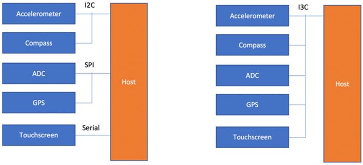
The MIPI I3C Bus interface is an evolutionary specification that builds upon the legacy I2C standard. The aim is to reduce the number of physical pins used in sensor system integration and supports low-power, high-speed digital communication typically associated with UART and SPI interfaces so that I3C becomes a single interface combining all the capabilities of the legacy interfaces.
I3C Protocol has a multi-drop bus which, at 12.5 MHz, is over 12 times faster than what I2C supports while using significantly less power.
I3C Protocol’s main features include:
- Backward compatibility with legacy I2C
- Multi-Master and Multi-drop capabilities
- Dynamic Addressing
- In-Band Interrupts
- Hot-Join support
The I3C Protocol interface is expected to play a fundamental role in streamlining sensor integration in smartphones, Internet-of-Things (IoT) devices, and wearables. I3C can also be used to manage complex systems as and when designers migrate to a common management transport which drastically reduces cost and latency in such complex systems while also enabling new capabilities.
MIPI I3C Theory of Operations: I3C Protocol
All I3C Protocol communications occur within a frame. The frame begins with a START, followed by one or more transfers, and a STOP.
The I3C interface supports Single Data Rate (SDR) messages which are similar to I2C Messages. The maximum clock speed is 12.5MHz. It also supports high data rate (HDR) messages. In HDR, data transfer is equivalent to clock cycles. There are two types of messages Broadcast and Direct common command code (CCC) messages which allows the master to communicate with all or specific slave on the bus.
I3C protocol is based on the frame encapsulation approach. The I3C frame always includes START, the Header, the data, and the STOP. The I3C bus is always initialized in SDR mode and never in HDR mode.
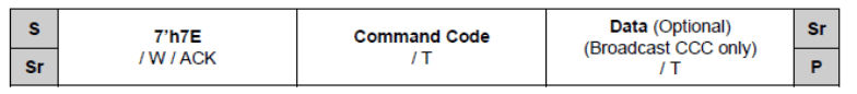
Common Command Code (CCC) commands protocol is formatted using only SDR. CCC is transmitted to specific to slaves or all slaves in the I3C bus. CCC General format is shown in this figure.
For the HDR modes:
- First the dedicated Broadcast I3C address(7’h7E) is issued to all slaves on the I3C bus.
- Then one of the Enter HDR CCCs is issued, indicating that the Master is entering the HDR mode. Each HDR mode has its own Enter HDR CCC.
- This is followed by one or more HDR transfers.
- HDR mode is ended by using the HDR exit pattern protocol.
For more details on I3C protocols, please refer to MIPI® I3C specifications.
I3C devices have Bus and Device characteristic registers which will hold information about the capabilities of I3C devices.
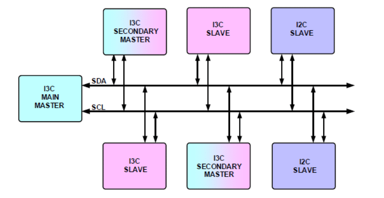
I3C bus can be configured with multiple devices. These devices are I3C Main Master, I3C Secondary Master, I3C Slave, and I2C Slave.
I3C devices may have many features appropriate for their function in the I3C bus. Depending on the I3C Bus system’s need, it may not be necessary that all features are enabled for any particular bus instantiation. Enabled features of every I3C device shall be described in the characteristic register of the device. Master obtains the characteristic register info during the power-up state of the I3C bus.
At the start-up stage from power-down, the main master shall assign a unique dynamic address to every device on the bus including itself. Dynamic address creates a priority ranking of device interrupts. If any secondary master present in the I3C bus shall be made aware of dynamic address and characteristic registers.
I3C-based electronic hardware design involves the design of I3C Master, I3C Slave, and I3C system designs. These designs offer different challenges at different stages of the design cycle. Design engineers need a tool to debug the I3C device for reliable operations. Some of the important requirements are
- Designers who are developing master or slave, need a fully working Master or Slave device which designers can configure and test their designs.
- Make sure I2C devices can co-exist with I3C bus
- They need a tool that will capture the communication between Master and slave and analyze the protocol traffic for protocol errors
- Need a tool to capture protocol traffic at a specific event. These events could be anticipated error conditions or protocol activity
- Emulate the I3C bus using the designed Master or Slave device in the I3C network
Where is I3C Protocol being used?
I3C protocol is used as a de-facto standard for integrating sensors in the System. Temperature sensors, gyroscopes, etc. There are new interesting applications for I3C interfaces in data centers as management buses.
Debugging I3C Tools :
When working with I3C, it is important to have the right set of tools to ensure the I3C design is implemented properly. Having a logic analyzer and oscilloscope is always helpful to debug complex hardware timing issues. There are cheaper tools available in the market to test I3C, however, limited in capability.
A logic analyzer is an excellent tool to debug when implementing and designing the I3C Bus. This can help you understand the protocol packet-level issues.
An oscilloscope is helpful in case you want to measure the timing parameters of the I3C Device.
I3C protocol analyzer can be very helpful to do I3C packet sniffing. Prodigy Technovations also offers an I3C Electrical Validation, and I3C Protocol Decode Software to debug your I3C packets using a Tektronix oscilloscope.
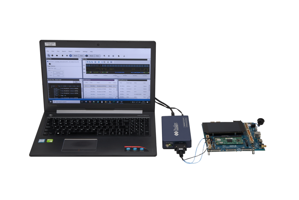
How does Prodigy Technovations Interfaces with I3C?
Prodigy Technovations has several different tools that interface with the I3C protocol. All the I3C tools fall into two different areas. The protocol analyzer monitors the traffic that is happening on the bus. The exerciser allows users to interface directly with I3C System and drive I3C Data.
Benefits of Prodigy’s I3C Protocol Exerciser and Analyzer:
- Ability to configure it as Master or Slave
- Ability to configure PID, BCR, and DCR registers
- Supports legacy I2C slaves and Master
- Generate different I3C and I2C SDR and HDR Packets
- Flexibility to upgrade the unit TSP and TSL encoding (When it is available)
- Error Injection such as CRC errors, parity errors, and ACK/NACK errors
- Variable I3C data speeds
- Simultaneously generate I3C traffic and Protocol decode of the Bus
- Timing diagram of Protocol decoded bus
- Listing view of Protocol activity
- Error Analysis in Protocol Decode
- State Machine view of the I3C packets
- Ability to write exerciser script to combine multiple data frame generation at different data speeds
- USB2/3 host computer interface
- Flexibility to upgrade to the unit for evolving I3C Specification