UART Protocol: INTRODUCTION
UART stands for Universal Asynchronous Receiver Transmitter. A UART’s main purpose is to transmit and receive serial data. UART was developed by Gordon Bell at Digital Equipment Corporation in the 1960s. UARTs are used in automobiles, smart cards, and SIMs in which they are commonly integrated in microcontroller chips.
In UART communication, the Transmitting UART converts parallel data to serial form and transmits it serially to the receiving UART, which then converts the serial data back into parallel data. Only two wires are needed to transmit data between the two UARTs. UART data bits are sent one by one, from the LSB to the MSB, framed by start and stop bits to precisely handle timing in the communication channel.
UART transmits bits asynchronously, which means that there is no clock signal to synchronize the output of bits from the transmitting UART to the sampling of bits by the receiving UART. Instead of a clock signal, the transmitting UART adds a start and stop bit to the data packet being transferred. Baud rate is a measure of the speed of data transfer, expressed in bits per second. Both UARTs must operate at the same baud rate. The standard baud rate is 9600bps which is sufficient for low-speed operations and it can reach speeds of up to 115200bps.
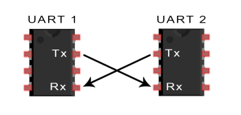
Figure 1. Transmitting and Receiving UART
UART Protocol: THEORY OF OPERATION
The Transmitter UART is the one that receives the data on a data bus from a CPU or microcontroller. After the transmitting UART gets the parallel data from the data bus, it adds a start bit, a parity bit, and a stop bit which makes a data packet. Next, the data packet is sent to the output serially, bit by bit. The receiving UART reads the data packet bit by bit and then converts the data back into parallel form removing the start bit, parity bit, and stop bits. After which, the receiving UART transfers the data packet in parallel to the data bus at the receiving end.
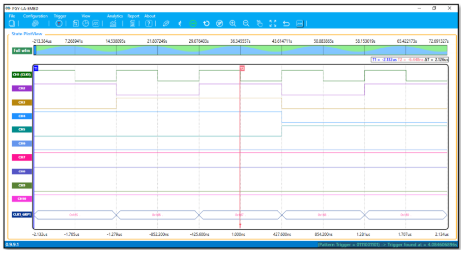
Figure 2. UART data packet
START BIT
To start the transfer of data, the transmitting UART pulls the transmission line from high to low for one clock cycle. When the receiving UART detects the high-to-low voltage transition, it begins reading the bits in the data frame at the frequency of the baud rate.
DATA FRAME
The data frame contains the actual data being transferred. It can be 5 bits if a parity bit is not used or up to 8 bits long if a parity bit is used. If no parity bit is used, the data frame can be 9 bits long. In most cases, the data is sent with the least significant bit (LSB) first.
PARITY
Parity is used for error checking in UART and it describes the evenness or oddness of a number. The parity bit is a way for the receiving UART to tell if any data has changed during transmission or not. Bits can be changed by mismatched baud rates or long-distance data transfers.
After the receiving UART reads the data frame, it counts the number of bits with a value of 1 and checks if the total is an even or odd number. If the parity bit is a 0 (even parity), the 1 bits in the data frame should total to an even number. If the parity bit is a 1 (odd parity), the 1 bits in the data frame should total to an odd number. When the parity bit matches the data, the UART knows that the transmission was free of errors. But if the parity bit is a 0, and the total is odd; or the parity bit is a 1, and the total is even, the UART knows that bits in the data frame have changed.
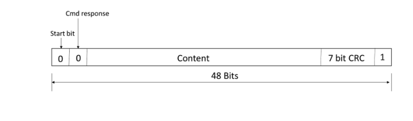
Figure 3. Odd and even parity UART
STOP BIT
To signal the end of the data packet, the sending UART drives the data transmission line from a low voltage to a high voltage for at least two-bit durations.
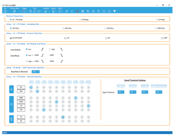
UART Protocol Analysis and Debug :
UART is a simple protocol however the analysis continues to remain a challenge. Prodigy Technovations has multiple solutions for the UART protocol analysis and Debug.
1. UART Protocol Analyzer and Exerciser.
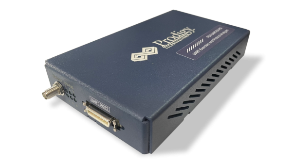
UART Protocol Analyzer and Exerciser
2. UART Protocol Analysis software.
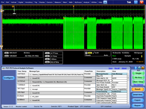
UART Protocol Analysis software.
3. Logic Analyzer with inbuilt UART protocol decode capability