

Controller Area Network (CAN) Protocol Debugging
What is CAN protocol?
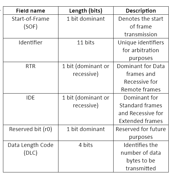
The Controller Area Network (CAN) is a serial communications protocol that supports distributed real-time control with a very high level of security and efficiency.
Where is CAN Protocol Used?
CAN is extensively used (but not restricted) in the automotive industry for automotive electronics precisely in the engine control units (ECUs), for various applications involving sensors, anti-skid systems, etc. The numerous ECU functions used in an automotive vehicle are managed by microcontrollers. To establish communication between the microcontrollers and devices with each other’s applications without needing a host computer, a bus architecture known as CAN is robustly designed.
How does CAN communicate?
CAN is a message-based protocol and for each device, the data in a frame is transmitted sequentially. The message onto the bus is transmitted serially using a Non-Return-to-Zero (NRZ) format.
CAN Protocol: Theory of Operations
Bit rate: The bit rate of a CAN bus in a given system is uniform and ranges up to a maximum of 1 Mbps (excluding CAN-FD). CAN-FD could have a variable bit rate in a given system and ranges up to a maximum of 5-8 Mbps.
Broadcast: CAN is a broadcasting type of communications protocol, in which the concept of ‘Master’ and ‘Slave’ is not present. Any device having an update over a specific activity from any application could transmit the corresponding frame and every other device on the bus could read this frame.
Arbitration: Since CAN is a broadcasting type of communication protocol, multiple devices tend to communicate at the same time. During such a condition, conflict on the bus is inevitable. To solve this type of problem, bitwise arbitration is adopted. Whichever device wins the arbitration, gets to communicate and others back off.
Error Detection: All CAN nodes are implemented with powerful measures for error detection, signaling, and self-checking, and these measures are:
- Monitoring (the bit levels of the data to be transmitted will be continuously compared by the transmitter with the bit levels detected on the bus).
- Cyclic Redundancy Check (CRC) – CRC is adopted to ensure that the data in the frame is received flawlessly.
- Bit stuffing – After every 5 consecutive homogeneous bits a bit with an opposite polarity is introduced. This is called bit stuffing.
Now let’s get into the CAN frame formats and the way they look.
CAN Frames Format :
The message transfer is done through four types of frames, and they are:
Data frames: Carries the data between transmitter and receiver
Remote frames: A bus unit can request the transmission of a data frame with the same Identifier by sending this remote frame to the transmitter.
Error frames: When a bus error is detected, an error frame is transmitted.
Overload frames: An overload frame is transmitted to provide an extra delay between frames (a standard amount of delay is provided by Interframe space) during multiple frames transmission.
Each Data frame and Remote frame has two different types of frame formats, and they are, Standard frame and Extended frame.
Alright, pictures speak more than words! Let us show the frames
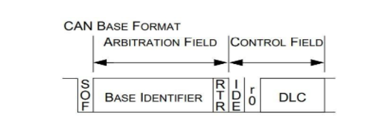
These fields are the same for both Data and Remote frames. The next fields are shown in the below figure.
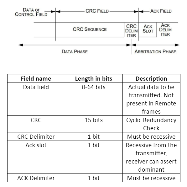
After all these fields, it is the End-of-Frame field which consists of seven consecutive 1’s, indicating the end of transmission.
Seven consecutive 1’s? What about bit stuffing then?
Well, bit stuffing is done only till the CRC-Delimiter field. The remaining fields are fixed in a frame. Hence, no bit stuffing is done to the Acknowledgement field and End of frame field.
Okay, now what’s the difference between the Standard frame and the Extended frame? As well as between the Data frame and Remote frame?
One at a time; The only difference between Standard and Extended frames is that the identifier is of 29-bits in Extended frames whereas, 11-bits in Standard frame formats. The 29-bits are categorized into two ID fields, first, 11-bits are as same as in the Standard frame and next 18-bits in another field. The below figure shows the difference between the two frames.
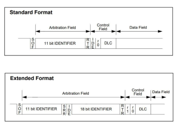
The SRR field is Substitute Remote Request, and it is transmitted as recessive.
Well, now with the Data frame and Remote frame. A data frame is shown in the above figure. The remote frame is the same as the Data frame except that the Data field is not present. So, it comprises of SOF, Arbitration field, Control field, CRC field, ACK field, and EOF.
Great! Next, what’s with that CAN-FD?
CAN-FD stands for CAN Flexible Data Rate. This was introduced to increase the bandwidth on the bus by increasing the bit rate. Meaning, the bit rate on a given system during the frame transmission could change to a higher speed.
Oh, that’s nice! What about the frame structure?
CAN-FD has a similar frame structure to that of normal CAN, and two different types of frame formats as that of normal CAN, standard and extended frames, but there are no Data frame and Remote frame concepts here. The below figure gives a clear idea about the same.
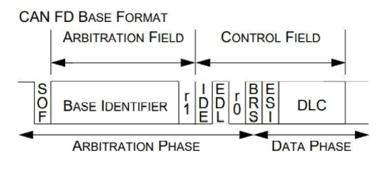
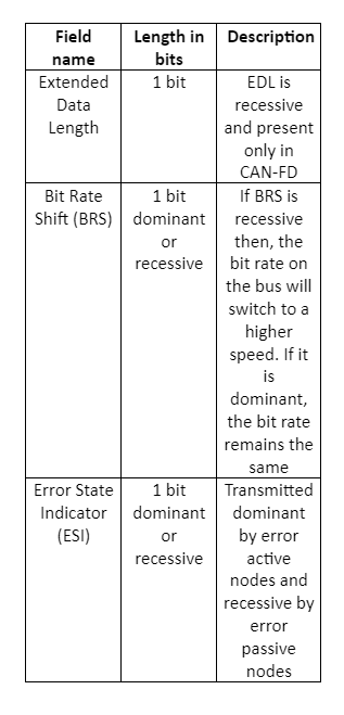
The only fields that are different from normal CAN are, EDL, BRS, and ESI
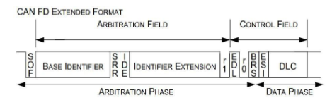
The CAN FD extended frame format consists of a 29-bit identifier and an SRR field which is recessive one bit. And the rest of the fields remain the same as that of the CAN FD standard frame format.
CAN Protocol Challenges in Debug
Well, the challenges during the debug are:
- Identifying different types of errors on the CAN bus
- Capture time for long data bytes and error checking for the same
Debugging CAN Protocol
To Debug CAN Protocol we need a very good protocol analyzer. Prodigy’s CAN Protocol Analyzer is capable of decoding every field in the frame and providing the user with the necessary information related to timing and data. The user can see this piece of information through the software UI.
The user can also set triggers for different conditions through the software GUI. The analyzer is then capable of triggering all the error conditions on the bus as well as at different fields in the CAN frame as set by the user. The analyzer constantly analyzes the bus for any errors and if found any, it reports, and this can be seen in the software UI.
The analyzer also checks for the CRC on the bus. Meaning, it receives the frame from the CAN Transmitter, decodes it, and calculates the CRC at its end. It displays the calculated CRC and the received CRC and throws an error if the comparison does not match. All this information can be viewed in the software UI.
The software is working in tandem with the hardware (Protocol Analyzer) and thus, the settings made through the GUI will be updated to the hardware and the analyzer then works accordingly.
Learn more about CAN Protocol Analyzer
About the Author :
Sumukha Bharadwaj is an FPGA Design Engineer at Prodigy Technovations. He graduated from the K S School of Engineering and Management in 2015 with a Bachelor’s degree in Electronics & Communication Engineering. He also completed his Master of Engineering, Information Technology from SRH Hochschule Heidelberg.
About Prodigy Technovations :
Prodigy has developed state of the art Protocol analyzer to debug various Protocols. The protocol analyzers range from CAN, I2C, SPI, QSPI, I3C, and UFS Plus many other protocols on the serial bus.

