SMBus Protocol
SMBus Protocol Introduction:
The System Management Bus (SMBus) is a two-wire interface through which various system component chips and devices can communicate with each other and with the rest of the system. It is based on the principles of operation of the I2C bus. SMBus provides a control bus for system and power management-related tasks.
SMBus is commonly used in personal computers for smart batteries, temperature control, and other low bandwidth system management communication. The original purpose of the SMBus was to define the communication link between an intelligent battery, a charger for the battery, and a microcontroller that communicates with the rest of the system. However, SMBus can also be used to connect a wide variety of devices including power-related devices, system sensors, inventory EEPROMs, communications devices, and more.
SMBus technology is used in Smart Battery Systems, or SBS, which is often implemented in portable devices such as laptop computers, mobile devices, and cameras for efficient battery management. Smart Battery Systems consist of a host, smart charger, and smart battery and use SMBus for these components to communicate with each other and the rest of the system. Smart Battery Systems are often beneficial to the battery life in portable devices. By using SBS, the battery can inform the charger about multiple aspects, including its capacity, ideal charging current, maximum charging time, and much more. Plus, because there is more precision with these variables, a Smart Battery doesn’t require recharging as frequently.
SMBus vs I2C:
- I2C defines input voltage levels as percentages of VCC, while SMBus operates with fixed input voltage levels. The I²C and SMBus specifications also specify the logic input threshold voltages, VIL and VIH, differently. The I²C specification requires that VIL be 30% of VDD and that VIH be 70% of VDD. The SMBus V3.0 specification has fixed thresholds. VIL is set to 0.8 V and VIH is set to 1.35 V.
- SMBus requires a minimum bus clock frequency of 10 kHz (Except when the bus is idle). I2C has no such requirement. The maximum frequency of SMBus is 100 kHz, which equals the maximum speed of I2C operating in standard mode.
- In I²C bus specification, the master may hold the clock line low forever and that would be a valid condition. In addition, the I²C specification permits a slave device to hold the clock line low for an unlimited amount of time. The SMBus specification places limits on the maximum amount of time a master may extend the clock low time within each byte of a message. There is also a limit on the total time a slave device may extend the clock low time within each message.
- The I²C specifications do not require that a device always acknowledge its address. This can confuse a system controller whether it is because the device is busy, has failed, or has been removed. To prevent this confusion, the SMBus specifications require that an SMBus device always acknowledge its address. If a device that did acknowledge its address fails to do so the system controller, then knows that the device has either failed or has been removed.
- For applications where power usage must be minimized, such as in battery-operated systems, the SMBus specification has a Low Power class. I²C does not have a similar specification.
SMBus Protocol Frame Format:
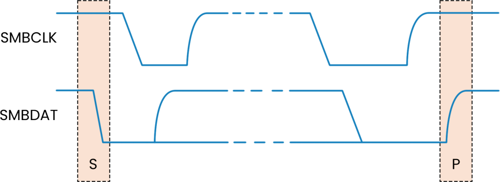
Two unique bus situations define a message START and STOP condition.
- A HIGH to LOW transition of the SMBDAT line, while SMBCLK is HIGH, indicates a message START condition.
- A LOW to HIGH transition of the SMBDAT line while SMBCLK is HIGH defines a message STOP condition. START and STOP conditions are always generated by the bus master. After a START condition, the bus is busy. The bus becomes idle again after a certain time following a STOP condition.
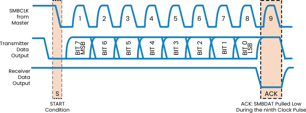
After the START condition (“S”), the master places the 7-bit address of the slave device it wants to address on the bus. The address is 7 bits long followed by an eighth bit indicating the direction of the data transfer (R/W#); a ZERO indicates a transmission (WRITE) while a ONE indicates a request for data (READ). A data transfer is always terminated by a STOP (P) condition generated by the master.
Every byte consists of 8 bits. Each byte transferred on the bus must be followed by an acknowledge bit. Bytes are transferred with the most significant bit (MSB) first.
The acknowledge-related clock pulse is generated by the master. The transmitter, master, or slave releases the SMBDAT line (HIGH) during the acknowledged clock cycle. To acknowledge a byte, the receiver must pull the SMBDAT line LOW during the HIGH period of the clock pulse. A receiver that wishes to NACK a byte must let the SMBDAT line remain HIGH during the acknowledged clock pulse. An SMBus device must always acknowledge (ACK) its address. SMBus uses this signaling to detect the presence of detachable devices on the bus. An SMBus slave device may decide to NACK a byte other than the address byte in the following situations:
- The slave device is busy performing a real-time task, or the data requested are not available. The master upon detection of the NACK condition must generate a STOP condition to abort the transfer. Note that as an alternative, the slave device can extend the clock LOW period within the limits of this specification to complete its tasks and continue the transfer.
- The slave device detects an invalid command or invalid data. In this case, the slave device must NACK the received byte. The master upon detection of this condition must generate a STOP condition and retry the transaction.
- If a master receiver is involved in the transaction it must signal the end of data to the slave transmitter by generating a NACK on the last byte that was clocked out by the slave. The slave transmitter must release the data line to allow the master to generate a STOP condition.
SMBus Protocol Theory of Operation:
The SMBus specification refers to three types of devices: host, master, and slave.
- A host is a specialized master that provides the main interface to the system’s CPU.
- A master is a device that issues commands, generates the clocks, and terminates the transfer.
- A slave is a device that receives or responds to a command.
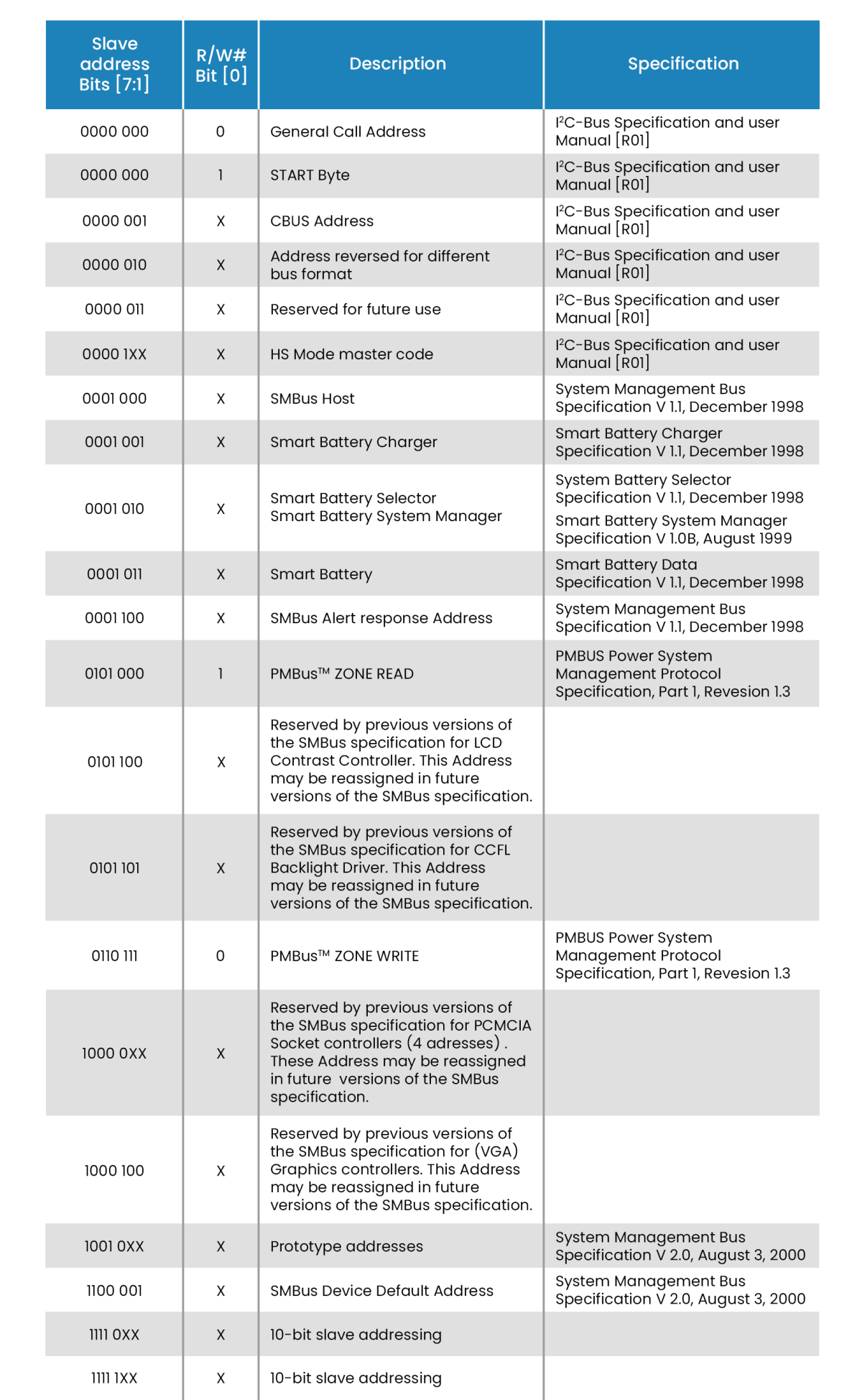
Each device that exists as a slave on the SMBus has one unique seven-bit address called the slave address. Each address is seven bits long with a read/write bit appended in bit position 0. When a device “sees” its address, it wakes up and responds to the rest of the command. Besides the General Call Address, SMBus systems can have 127 devices.
A typical SMBus device will have a set of commands by which data can be read and written. All commands are one byte long while their arguments and return values can vary in length. Accessing a command that does not exist or is not supported may cause an error condition. By the SMBus specification, the most significant bit (MSB) is transferred first.
All the commands first put a start condition on the bus, then begin the transmission by transmitting the command/data, wait for an acknowledgment from the slave (receiving) device during command/data transmission, and then put a stop condition on the bus.
Following is a description of some basic SMBus command protocols:
Quick command—The R/W bit in the slave address denotes the commands. An example of using it is to turn it on/off or to enable/disable a device function. There is no data sent or received.
Send byte—The data byte sent contains the features to be accessed and actions for this feature to execute.
Receive byte—The Receive byte is like a Send byte; the only difference is the direction of data transfer. The Receive byte is used when the host accesses the device for some information.
Packet Error Checking
The Packet Error Checking mechanism improves reliability and communication robustness. Packet Error Checking, whenever applicable, is implemented by appending a Packet Error Code (PEC) at the end of each message transfer. Each protocol (except for Quick Command and the host notify protocol) has two variants: one with the Packet Error Code (PEC) byte and one without. The PEC is a CRC-8 error-checking byte, calculated on all the message bytes (including addresses and read/write bits). The PEC is appended to the message by the device that supplied the last data byte.
Synchronization
A situation may occur in which more than one master is trying to place clock signals on the bus at the same time. The resulting bus signal will be the wired-AND of all the clock signals provided by the masters. A high-to-low transition on the SMBCLK line will cause all devices involved to start counting off their LOW period and start driving SMBCLK low if the device is a master. As soon as a device finishes counting its LOW period it will release the SMBCLK line. Nevertheless, the actual signal on the SMBCLK may not transition to the HIGH state if another master with a longer LOW period keeps the SMBCLK line LOW. In this situation, the master that released the SMBCLK line will enter the SMBCLK HIGH wait period. When all devices have counted off their LOW period, the SMBCLK line will be released and go HIGH. All devices concerned at this point will start counting their HIGH periods. The first device that completes its HIGH period count will pull the SMBCLK line LOW and the cycle will start again.
Arbitration
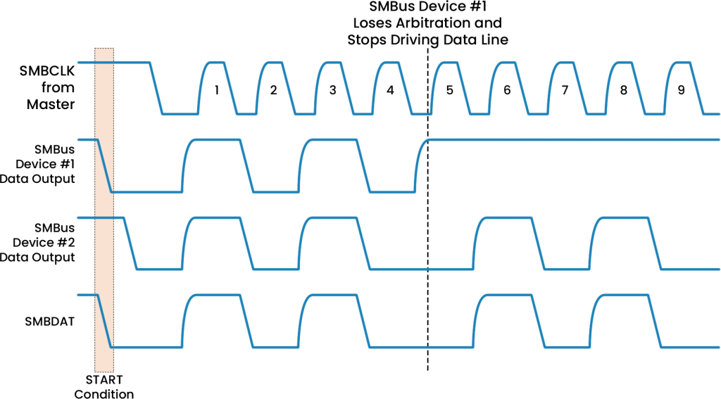
A master may start a transfer only if the bus is idle. One or more devices may generate a START condition within the minimum hold time resulting in a defined START condition on the bus.
Since the devices that generated the START condition may not be aware that other masters are contending for the bus, arbitration takes place on the SMBDAT line while the SMBCLK is HIGH. A master that transmits a HIGH level, while another master (or masters) is transmitting a LOW level on the SMBDAT line loses control of the bus in the arbitration cycle.
This mechanism requires that SMBus master devices participating in an arbitration cycle monitor the actual state of the SMBDAT line during the arbitration.
ABOUT THE AUTHOR
Anuj is an FPGA Design Engineer at Prodigy Technovations. He graduated from NMAM Institute of Technology with a bachelor’s degree in Electronics and Communication Engineering. He has hands-on experience in debugging and fixing hardware issues reported during product development and has rich experience in resolving customer issues during product evaluation.
Prodigy’s SMBus Protocol Exerciser and Analyzer
SM Bus Serial bus interface has been widely used for voltage and temperature monitoring of the system. PGY-SMBus-EX-PD is the leading instrument that enables the design and test engineers to test the SM Bus designs for its specifications by configuring PGY-SM Bus -EX-PD as master/slave, generating SM Bus traffic with error injection capability and decoding SM bus Protocol decode packets.


