INTRODUCTION TO LOGIC ANALYZER
A logic analyzer is an electronic instrument that captures and displays multiple signals from a digital system or a digital circuit. It is an excellent tool for verifying and debugging digital designs. A logic analyzer may convert the captured data into timing diagrams, protocol decodes, state machine traces, and assembly language. For debugging elusive, intermittent problems, some logic analyzers can detect glitches, as well as setup-and-hold time violations. During software/hardware integration, logic analyzers trace the execution of the embedded software and analyze the efficiency of the program’s execution. Some logic analyzers correlate the source code with specific hardware activities in your design.
A logic analyzer is used when we need to
- Debug and verify digital system operation.
- Trace and correlate many digital signals simultaneously.
- Detect and analyze timing violations and transients on buses.
- Trace embedded software execution.
THE LOGIC ANALYZER
Debugging microprocessor-based designs required more inputs than what conventional analog oscilloscopes could offer. A typical logic analyzer has anywhere from 8 to 136 channels, and they are particularly useful for looking at time relationships or data on a bus. For example, a microprocessor address, data, or control bus. They can decode the information on microprocessor buses and display it in a meaningful form.
A logic analyzer measures and analyzes signals differently than an oscilloscope. The logic analyzer does not measure analog details. Instead, it detects logic threshold levels. When we connect a logic analyzer to a digital circuit, we are only concerned with the logic states of the signal, i.e., a logic analyzer looks for just two logic levels. When the input is above the threshold voltage (V) the level is said to be a “high” or “1”; conversely, the level below Vth is a “low” or “0”. When a logic analyzer samples input it stores a “1” or a “0” depending on the level of the signal relative to the voltage threshold.
HISTORY OF LOGIC ANALYZER
Circuits started becoming smaller after the invention of the Integrated circuit (IC) in the early 1960s. While technology further developed over the years, there was an increase in the computational power and speed of digital circuits. Due to this reason, testing and debugging electronic devices proved to be difficult as thousands and millions of transistors could be packed inside a single chip which reduced their overall size and increased the number of pins. Hence, logic analyzers proved to be an important tool in analyzing electronic circuits due to their ability to time correlate a large number of signals on a single display which made it easier to view data movement and processing within many embedded systems or the peripherals of small computer systems.
Hewlett Packard announced the invention of the first logic analyzer in 1973 which was capable of measuring and displaying logic states across a set of LEDs. The HP 5000A was the first commercially available logic analyzer and had two channels.
TYPES OF LOGIC ANALYZERS
There are three types of logic analyzers: modular logic analyzers, portable logic analyzers, and PC-based logic analyzers.
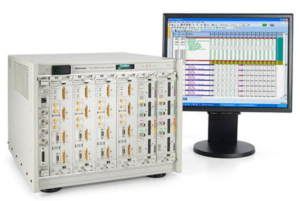
Modular Logic Analyzers: Modular logic analyzers are the standard form seen in labs that have a chassis and multiple modules. These are one of the more expensive and provide the highest level of functionality to the user.
Figure 2. Modular Logic Analyzer
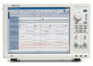
Portable Logic Analyzer: Portable logic analyzers are more portable than modular logic analyzers and provide all the functions that are integrated into a single module with a screen.
Figure 3. Portable Logic Analyzer
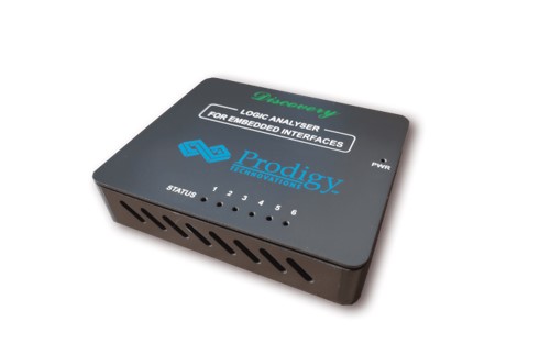
PC-based Logic Analyzer: PC-based logic analyzers are compact and they directly interface to a computer via an ethernet or a USB cable. The captured information is displayed to the user via the PC’s display. PC-based logic analyzers are the least expensive but are limited in terms of power compared to modular and portable logic analyzers.
Figure 4. PC-Based Logic Analyzer From Prodigy Technovations
ABOUT AUTHOR
Raghavendra Bhat is an Application Engineer at Prodigy Technovations. He graduated from NMAM Institute of Technology in 2020 with a bachelor’s degree in Electronics & Communication Engineering. His area of interest includes Embedded systems, Digital System Design, and Automotive Electronics.
For more information reach out to us at (contact@prodigytechno.com)


