

SPMI Protocol – System Power Management Interface Protocol
SPMI Protocol Introduction
The complexity and performance requirements of mobile phones and other portable electronic devices are increasing at an exponential rate. As the demand for new high-performance, high-data-rate feature increase, system-level power management becomes critical. The use of advanced power management techniques to reduce power consumption and improve battery life is becoming more important than ever before.
To minimize the power consumption of digital processors in portable electronic devices, system, and IC designers are now using advanced power management techniques. Advanced hardware and software techniques are now being used to:
- Accurately monitor and control processor performance level required for a given workload or application.
- Control various supply voltages based on the performance level Rapid deployment of such advanced power management techniques requires interface standardization. This System Power Management Interface Protocol (SPMI Protocol) Specification addresses hardware interface standardization.
What is SPMI Protocol?
The System Power Management Interface Protocol (SPMI Protocol ) is a MIPI standard interface that connects the integrated Power Controller (PC) of a System-on-Chip (SoC) processor system with one or more Power Management Integrated Circuits (PMIC) voltage regulation systems. SPMI Protocol enables systems to dynamically adjust the supply and substrate bias voltages of the voltage domains inside the SoC using a single SPMI Protocol bus.
Within the PC of SoC, the SPMI Protocol-related functions are referred to as “Master”. Within PMIC, the SPMI Protocol related functions are referred to as “Slave”. There can be up to 4 Masters and up to 16 Slaves. Multiple Masters and Slaves can reside on a single IC, on several ICs, or on any combination of the two.
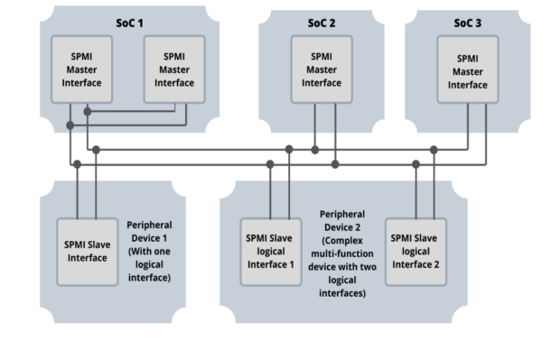
(fig:1)
SPMI Protocol has a wide range of applications that are spread across industries that needs better Power Management. SPMI Protocol is used in Smartphones, Wearables, and other portable electronic devices. Smartphones & Wearables use SPMI Protocol for controlling the power of sensors. High-end smartphones already have multiple devices in the designs & can require up to 20 signal lines. Each of these having independent power pins can cause issues. Similarly, most portable electronic devices would need a power management interface to optimize energy consumption and reduce pin count. This requires a standardized advanced power management interface.
SPMI Protocol: Theory of operation
SPMI Protocol is a two-wire serial interface for advanced power management that connects the integrated Power Controller of an SoC processor system with one or more Power Management Integrated circuits (PMIC) voltage regulation systems. The bi-directional two lines represent the SDATA & SCLK. SDATA is a bi-directional data line and the SCLK is controlled by the master.
The SPMI protocol has the following features
- Bus Arbitration is the process where the bus shall be allocated to one Master or Request capable Slave among the devices that may simultaneously request to send a command sequence on the bus.
- Master connection and disconnection – A process for a Master to connect to, & disconnect from, an initialized or uninitialized SPMI Protocol bus
- Slave-initiated communication – A process for a Request Capable Slave (RCS) to initiate communication with a Master or other Slaves.
- There are two defined SPMI Protocol device classes:
- High-speed (HS): 32 KHz to 26MHz, with load up to 50 pF
- Low speed (LS): 32KHz to 15MHz, with load up to 50 pF
- ACK/NACK for robust communication.
The sequences shall be comprised of the following five events that occur in order:
- Bus Arbitration
- Transmission of the Sequence Start Condition (SSC)
- Transmission of Frames (Command Frame and one or more Data frames)
- Transmission of ACK/NACK for command sequences.
- Transmission of a Bus Park Cycle
The last four events SSC, Command/Data Frames, ACK/NACK & Bus Park Cycle together form the command sequence. The SPMI Protocol specification constructs all command sequences on the interface using individual bits.
The Sequence Start condition shall be a unique condition on the bus identified by a rising edge followed by a falling edge on SDATA while SCLK remains at a logic low level. The SSC is used by a Slave or master to identify the start of a command sequence. SDATA is driven by the Bus Owner Master to a logic level one for one SCLKint period, then to logic 0 levels for one SCLKint period while holding the SCLK at logic zero.
There are three basic types of frames:
- Command Frame shall consist of 13 bits with a 4-bit address field, an 8-bit command field, and a single parity bit.
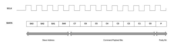
(fig:2)
OR
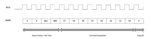
(fig:3)
- Data and Address frames consist of 9 bits with 8 bits of data or address and a single parity bit.
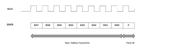
(fig:4)
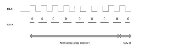
- No Response Frame of 9-bits long if it is a Data Frame or 13-bits if it is a command frame.
(fig:5)
Bus Arbitration is used to determine access to a bus for Master/s or Slave/s. Bus Owner Master monitors the arbitration and determines who gets access to the Bus. The different Bus arbitration levels are exposed after arbitration request in order as shown in the image below.
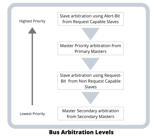
(fig:6)
Debugging SPMI Protocol :
Prodigy’s SPMI Exerciser and Protocol Analyzer play an important role in helping the design/ test engineers test their SPMI Protocol designs based on the SPMI specification. The typical test setup for testing Master or Slave is as below.
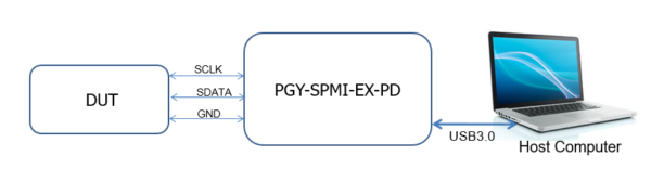
(fig:7)
SPMI Protocol DUT can be an SPMI Protocol Primary Master, Secondary Master, Request Capable Slave, or Non-Request Capable Slave. The software that runs in the host computer enables the user to configure the device as either a master or slave based on the requirement in DUT by selecting the appropriate selection.
SPMI Exerciser and Protocol Analyzer

SPMI Electrical Validation and Protocol Decode Software
SPMI Protocol Signals can be initiated by using the GUI or custom SPMI Protocol packets can be initiated by writing or using existing scripts from the exerciser panel. On generating the SPMI Protocol signals, the protocol analyzer captures the exchange of SPMI Protocol packets between master and slave. The captured information is decoded and listed in the decoded result view panel and the plot is made in the timing diagram window.
Conclusion
Prodigy offers an SPMI Protocol analyzer to help debug designs with the SPMI Protocol interface. Prodigy has a team of experienced engineers working on advanced debug interfaces and protocols to help design engineers.

