I2C Clock Stretching
Introduction: I2C Protocol
I2C Protocol stands for Inter Integrated-Circuit. I2C is a simple two-wire design, half-duplex serial communication protocol, and the data is transmitted bit by bit over a single wire. I2C supports multiple masters and slaves on the bus, but only one master can be active at a time. Any I2C device can be attached to the bus allowing any master device to exchange information with a slave device. A device can operate either as a transmitter or a receiver depending on its function. Initially, I2C only used 7-bit addressing but evolved to allow 10-bit addressing as well. Three bitrates are supported: 100 kb/s (standard mode), 400 kb/s (fast mode) and 3.4 Mb/s (high-speed mode).
I2C Frame format:
- Start indicates the start of operation and the device taking control that a message will follow.
- ddress is a 7-bit/10-bit number representing the address of the device that will either be read from or written to.
- R/W bit is a bit indicating whether the data will be read from or written to the device.
- ACK is a bit from the slave device acknowledging the master’s action.
- Data is an integer number of bytes read from or written to the device.
- Stop indicates the message is complete and the master has released the bus.
Figure 1: I2C Frame Format
I2C Protocol: Theory of Operation:
I2C’s physical two-wire interface consists of bi-directional serial clock (SCL) and data (SDA) lines. Both SCL and SDA lines must be connected to Vcc through a pullup resistor. Data transfer is initiated only when the bus is idle. A bus is considered idle if both SDA and SCL lines are high after a stop condition.
I2C communication on the bus is initiated by the master sending a START condition and terminated by the master sending a STOP condition. A high-to-low transition on the SDA line while the SCL is high defines a START condition. A low-to-high transition on the SDA line while the SCL is high defines a STOP condition.
Repeated START condition is useful when the master wishes to start a new communication but does not wish to let the bus go idle with a STOP condition. Sending a stop condition can cause the master to lose control of the bus to another master (in multi-master environments). Hence, a repeated start condition is used. Here, instead of sending the STOP condition, the master sends another START condition followed by the address, read/write bit, and data. For generating a repeated START, the master changes the SDA line from high to low while the SCL line is high. In case the I2C bus remains busy, the master sets the SDA line to high during the low phase of the SCL to prepare for the repeated START condition.
One data bit is transferred during each clock pulse of the SCL. One byte consists of eight bits on the SDA line. A byte may either be a device address, register address, or data written to or read from a slave. Data is transferred the most significant bit (MSB) first. Any number of data bytes can be transferred from the master to the slave between the START and STOP conditions. Data on the SDA line must remain stable during the high phase of the clock period, as changes in the data line when the SCL is high are interpreted as control commands (START or STOP).
Each byte of data including the address byte is followed by one ACK bit from the receiver. The ACK bit allows the receiver to communicate with the transmitter that the byte was successfully received, and another byte may be sent. Before the receiver can send an ACK, the transmitter must release the SDA line. For all data bits, including the acknowledge bit, the master must generate clock pulses. If the slave device does not acknowledge the transfer, this means that there is no more data, or the device is not ready for the assignment yet.
The 9th clock cycle of SCL is for the ACK and NACK. The acknowledge signal is valid when the transmitter releases the SDA line during the acknowledge clock pulse. If the receiver pulls the SDA line low, and it remains at a stable low during the high period of the clock pulse, it indicates ACK. If the SDA line is drawn to high, then that signifies NACK.
Data must be sent and received to or from the slave devices, but the way in which it is accomplished is by reading or writing to or from registers in the slave device.
Figure 2: Data Transfer on the I2C bus
Clock Stretching in I2C Protocol:
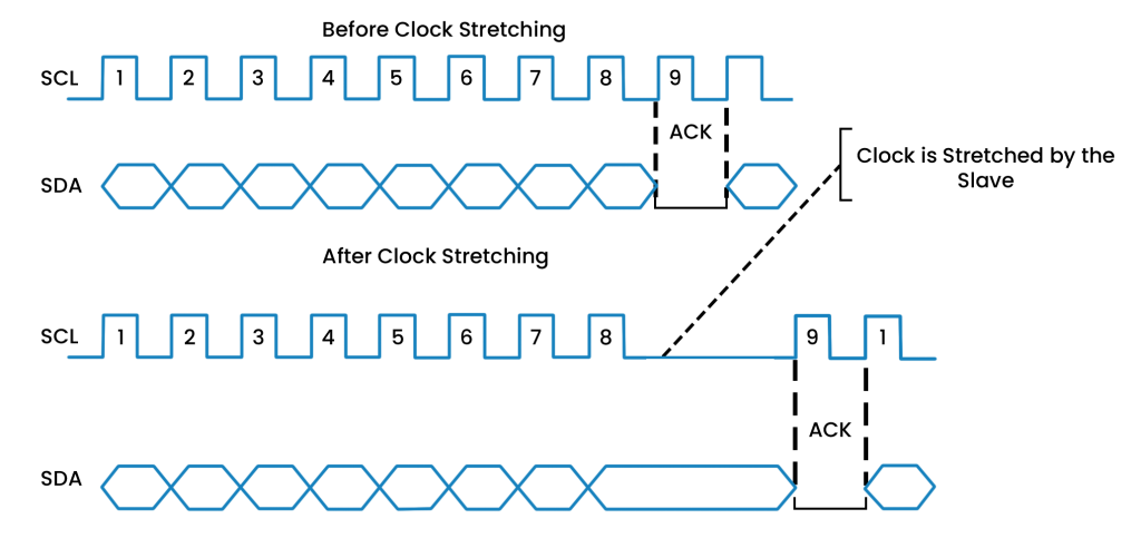
An I2C master controls the clock speed and provides SCL on the line. It is possible for the slave device to “stretch” or hold the clock and alt the data or commands transmission from the master. Clock stretching is mainly used to hold the master device when the slave device is swamped. An I2C slave device can use clock stretching to push the master device into a wait state. When a slave device requires longer time to manage data, such as store received data or prepare to transmit another byte of data, it may execute clock stretching. This usually happens after the slave device has acknowledged receiving a byte of data.
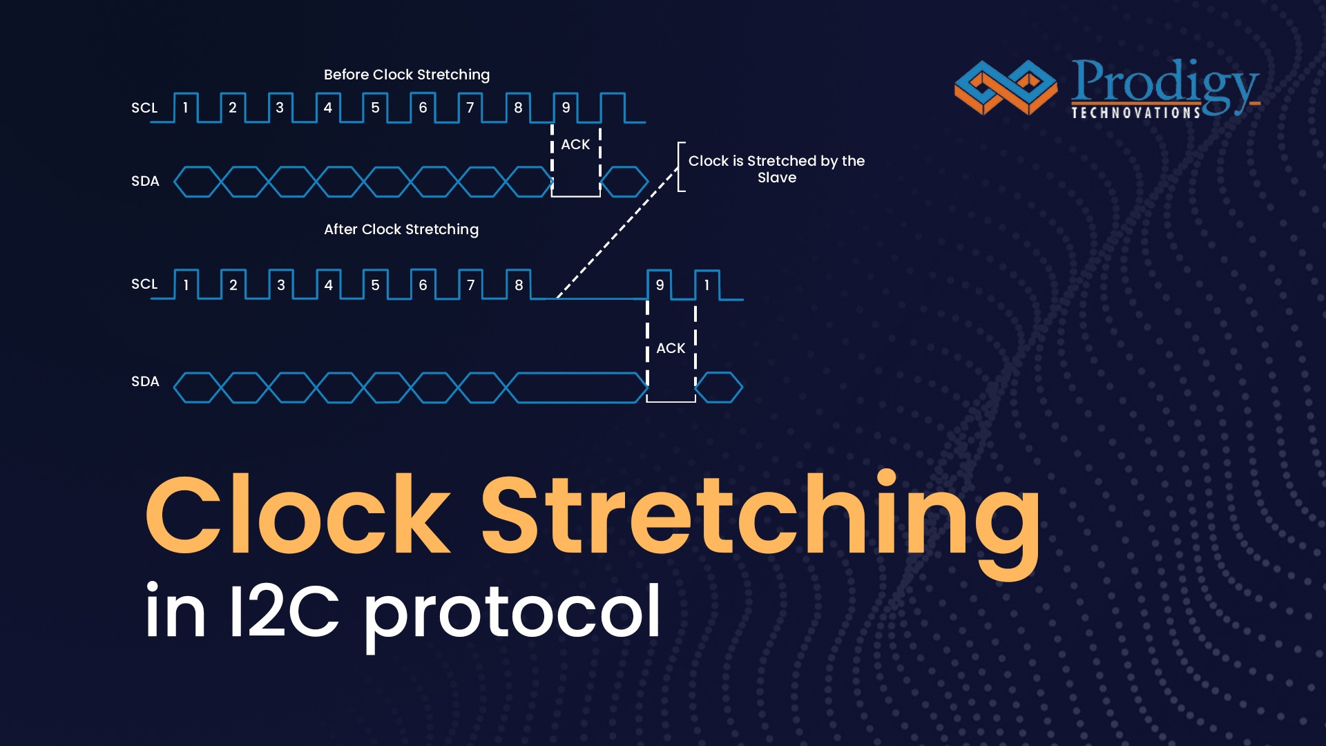
Figure 3: Illustration of Clock stretching in I2C
The clock stretching pauses the transaction by holding the SCL line LOW. The data transaction cannot be completed until SCL line held HIGH. Clock stretching is optional and in fact, most target devices do not include an SCL driver, so they are unable to stretch the clock.
A device may be able to receive bytes of data quickly at the byte level, but it takes longer to store a received byte or prepare another byte for transmission. After receiving and acknowledging a byte, targets can keep the SCL line LOW to force the controller into a wait state until the target is ready for the next byte transfer, like a handshake operation.
A device, such as a microcontroller with or without limited I2C-bus hardware, can slow down the bus clock by lengthening each clock LOW period on the bit level. Any controller’s speed is adjusted to the device’s internal operating rate.
Clock Stretching using PGY_I2C_EX_PD:
Prodigy offers an I2C Protocol analyzer to capture and decode the I2C packets. I2C protocol analyzer has the advanced capability not only to trigger but long allow very long captures which is very useful for the embedded design engineer during the debug.
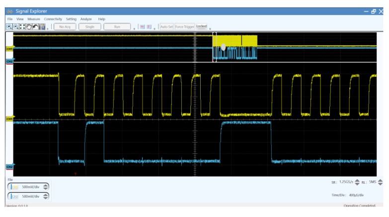
Figure 4: Capture of I2C Clock Stretching
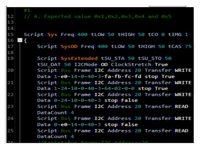
Figure 5:PGY_I2C_EX_PD Script
PGY_I2C_EX_PD supports I2C clock stretching in both master and slave devices in Open Drain Mode only. In the above figure, the line in yellow signifies the SCL clock and the line in blue is Data line (SDA). The SCL clock is running at 400KHz. On the 9th clock of every I2C data transfer, the I2C slave pushes the SCL line low (before the ACK stage). The length of a clock stretching period is not limited by the I2C protocol. As the SCL line remains LOW for a certain amount of time, the SDA line is held HIGH. I2C clock stretching can be enabled using the script shown below in PGY_I2C_EX_PD.


