I2C Bus
Introduction to I2C Bus:
I2C stands for Inter-Integrated Circuit. Philips Semiconductors developed I2C in the early 1980s as a low-cost solution for connecting lower-speed peripheral ICs to processors and microcontrollers over short distances. Since then, I2C has evolved into a worldwide standard for communication between devices in embedded systems. The simple two-wire design can be used in applications like I/O, A/Ds, D/As, temperature sensors, microcontrollers, microprocessors, etc.
I2C is a half-duplex serial communication protocol and data is transferred bit by bit along a single wire. I2C supports multiple masters and slaves on the bus, but only one master may be active at a time. Any I2C device can be attached to the bus allowing any master device to exchange information with a slave device. A device can operate either as a transmitter or a receiver depending on its function. Initially, I2C only used 7-bit addressing but evolved to allow 10-bit addressing as well. Three bitrates are supported: 100 kb/s (standard mode), 400 kb/s (fast mode), and 3.4 Mb/s (high-speed mode).
The I2C standard specifies the following format as shown below:
Figure 1. I2C Frame Format
- Start – indicates that a device is taking control of the bus and that a message will follow.
- Address – a 7 or 10-bit number representing the address of the device that will either be read from or written to.
- R/W Bit – one bit indicating if the data will be read from or written to the device.
- Ack – one bit from the slave device acknowledging the master’s actions.
- Data – an integer number of bytes read from or written to the device.
- Stop – indicates the message is complete and the master has released the bus.
I2C THEORY OF OPERATION
I2C uses a controller known as the master to communicate with slave devices. A slave may not transmit data unless it has been addressed by the master. Each device is recognized by a unique address to differentiate between other devices that are on the same I2C bus. I2C’s physical two-wire interface consists of the bi-directional serial clock (SCL) and data (SDA) lines. Both SCL and SDA lines must be connected to Vcc through a pullup resistor. Data transfer is initiated only when the bus is idle. A bus is considered idle if both SDA and SCL lines are high after a stop condition.
I2C START AND STOP CONDITIONS
I2C communication on the bus is initiated by the master sending a START condition and terminated by the master sending a STOP condition. A high-to-low transition on the SDA line while the SCL is high defines a START condition. A low-to-high transition on the SDA line while the SCL is high defines a STOP condition.
Figure 2. I2C Start and Stop Conditions
I2C REPEATED START
A repeated START condition is useful when the master wishes to start a new communication but does not wish to let the bus go idle with a STOP condition. Sending a stop condition can cause the master to lose control of the bus to another master (in multi-master environments). Hence, a repeated start condition is used. Here, instead of sending the STOP condition, the master sends another START condition followed by the address, read/write bit, and data. For generating a repeated START, the master changes the SDA line from high to low while the SCL line is high. In case the I2C bus remains busy, the master sets the SDA line to high during the low phase of the SCL to prepare for the repeated START condition.
Figure 3. Repeated START Condition
I2C DATA FORMAT
One data bit is transferred during each clock pulse of the SCL. One byte consists of eight bits on the SDA line. A byte may either be a device address, register address, or data written to or read from a slave. Data is transferred to the most significant bit (MSB) first. Any number of data bytes can be transferred from the master to the slave between the START and STOP conditions. Data on the SDA line must remain stable during the high phase of the clock period, as changes in the data line when the SCL is high are interpreted as control commands (START or STOP).
I2C ACK BIT :
Each byte of data including the address byte is followed by one ACK bit from the receiver. The ACK bit allows the receiver to communicate with the transmitter that the byte was successfully received, and another byte may be sent. Before the receiver can send an ACK, the transmitter must release the SDA line. For all data bits, including the acknowledge bit, the master must generate clock pulses. If the slave device does not acknowledge the transfer, this means that there is no more data, or the device is not ready for the assignment yet.
The 9th clock cycle of SCL is for the ACK and NACK. The acknowledge signal is valid when the transmitter releases the SDA line during the acknowledge clock pulse. If the receiver pulls the SDA line low, and it remains at a stable low during the high period of the clock pulse, it indicates ACK. If the SDA line is drawn too high, then that signifies NACK.
Several conditions lead to the generation of a NACK:
- The receiver is unable to receive or transmit because it is performing some real-time function and is not ready to start communication with the master.
- During the transfer, the receiver gets data or commands that it does not understand.
- During the transfer, the receiver cannot receive any more data bytes.
- A master receiver is done reading data and indicates this to the slave through a NACK.
I2C DATA:
Data must be sent and received to or from the slave devices, but how it is accomplished is by reading or writing to or from registers in the slave device.
Registers are locations in the slave’s memory that contain information. Information can be in the form of configuration or some data that is to be sent back to the master. The master must write information into these registers to instruct the slave devices to perform a task.
Figure 4. Data Transfer using the I2C Interface
DEBUG TOOLS FOR I2C Bus: HOW TO DEBUG I2C Bus:
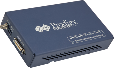
Prodigy also offers an I2C Protocol analyzer to capture and decode the I2C packets. The I2C protocol analyzer has the advanced capability not only to trigger but long allow very long captures which is very useful for the embedded design engineer during the debugging.
Have an I2c-related query? Post here – Prodigy Forum
About the Author
Raghavendra Bhat is an Application Engineer at Prodigy Technovations. He graduated from NMAM Institute of Technology in 2020 with a bachelor’s degree in Electronics & Communication Engineering. His area of interest includes Embedded systems, Digital System Design, and Automotive Electronics.
For more information reach out to us at (contact@prodigytechno.com)


