

HDMI Protocol
Introduction
HDMI is a digital replacement for existing analog video standards. It is termed as the catalyst for the DTV revolution. The DTV revolution is driving the HDMI standard to support an increase in data speed to higher video resolutions to meet emerging needs. As a result, design and validation engineers need tools to improve efficiency by performing a wide range of standards-required tests quickly and reliably.
HDMI protocol overview
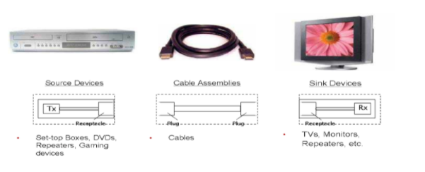
Fig 1 Source, Cable, and Sink devices
HDMI: High Definition Multimedia Interface, a compact uncompressed digital video and audio interface. HDMI system architecture is defined to consist of sources and sinks. A given device may have one or more HDMI inputs and one or more HDMI outputs. Each HDMI input on these devices has to follow all of the rules for an HDMI sink and each HDMI output shall follow all of the rules for an HDMI source.
HDMI cables and connectors carry four differential pairs that make up the TMDS data and clock channels. These channels are used to carry video, audio, and auxiliary data. In addition, HDMI carries a VESA DDC channel. The DDC is used for configuration and status exchange between a single source and a single sink. The optional CEC protocol provides high-level control functions between all of the various audiovisual products in a user’s environment.
Protocol Overview:
The HDMI link operates in one of three modes: Video Data Period, Data Island period, and Control period. During the Video Data Period, the active pixels of an active video line are transmitted. During the data island period, audio and auxiliary data are transmitted using a series of packets. The control period is used when no video, audio, or auxiliary data needs to be transmitted.
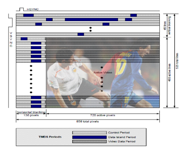
Fig 2 Video and Audio data pictorial representation
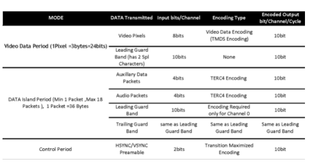
Table 1 HDMI Data Modes
Video Data Period: Video data periods are used to carry the pixels of an active video line. Each video data period is preceded by a preamble. Following the preamble, the video data period begins with a two-character video leading guard band. There is no trailing guard band for the video data period. In active video periods, 24 bits of pixel data are encoded using TMDS transition minimized encoding during each TMDS clock period.
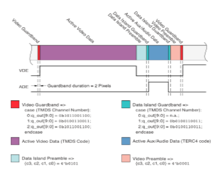
Fig 3 Video and Audio Data representation
Data Island Period: During the data island period, audio and auxiliary data are transmitted using a series of packets. This auxiliary data includes info frames and other data describing the active audio or video stream or describing the source. Each data island is preceded by a preamble. Following the preamble, each Island starts with a leading guard band. The first packet of the data island then follows. During every TMDS clock period of the data island, including the guard band, bits 0 and 1 of TMDS channel 0 transmit an encoded form of HSYNC and VSYNC. Bit 2 of TMDS channel 0 is used to transmit the packet header. All four bits of TMDS channels 1 and 2 are used for the packet data. Each packet is 32 pixels long and is protected by BCH ECC for error detection and correction.
During the data island, each of the three TMDS channels transmits a series of 10-bit characters encoded from a 4-bit input word, using TMDS Error Reduction Coding (TERC4). TERC4 significantly reduces the error rate on the link by choosing only 10-bit codes with high inherent error avoidance.
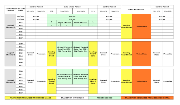
Fig 4 Video/Audio data on TMDS Data Channel
Control Period: The Control period is used when no video, audio, or auxiliary data needs to be transmitted. A control period is required between any two periods that are not control periods.
The control period is used for the transmission of the preamble. The sink for character synchronization also uses the control period.
During control periods, 2 bits per channel, or 6 bits total are encoded per TMDS clock using a transition-maximized encoding. These 6 bits are HSYNC, VSYNC, CTL0, CTL1, CTL2, and CTL3. Near the end of every control period, a preamble, using the CTLx bits, indicates whether the next data period is a video data period or a data island period.
Preamble: Immediately preceding each video data period or data island period is the preamble. This is a sequence of eight identical control characters that indicate whether the upcoming data period is a video data period or a data island. The values of CTL0, CTL1, CTL2, and CTL3 indicate the type of data period that follows. The remaining control signals, HSYNC and VSYNC, may vary during this sequence.
| CTL0 | CTL1 | CTL2 | CTL3 | Data Period Type |
| 1 | 0 | 0 | 0 | Video Data Period |
| 1 | 0 | 1 | 0 | Data Island Period |
Table 2 Data Period Type
Challenges in Validating HDMI Protocol
An HDMI technology provider needs to comply with the HDMI specification provided by the HDMI/MHL consortium. The HDMI/MHL protocol analysis software embeds the HDMI1.4a and MHL 2.0 Compliance Test procedure, ensuring dependable results. There are several tests to be carried out at the protocol layer. This test requires complex measurement techniques using dedicated HDMI/MHL protocol analyzers. These instruments offer engineers visibility into the logic state of the signal without correlation to the clock and data. Many times, protocol irregularities are hidden in the electrical signals in the PHY layer and logical layer.
Some of the drawbacks and challenges faced by the engineers during validation are listed below:
- Lack of a single tool or instrument to handle physical and Protocol layer challenges
- Difficulty in correlating the data from Protocol with the Physical layer
- Increasing complexity of the test system due to multiple pieces of equipment.
- There are no instruments that provide overhead information along with payload (actual image)
- No seamless synchronization possible from mapping the failure of a protocol test to actual
HDMI Protocol Analysis Software
The industry’s first oscilloscope-based TEK-PGY-HDMI/MHL Protocol Analysis software analyzes every event in the HDMI stream from HDMI/MHL frame including the phy layer which conventional protocol analyzers cannot accomplish.
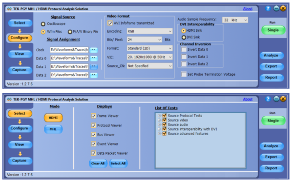
Prodigy’s HDMI Protocol Analysis Software
About Prodigy Technovations Pvt Ltd
Prodigy Technovations Pvt Ltd (www.prodigytechno.com) is a leading global technology provider of Protocol Decode, and Physical layer testing solutions on test and measurement equipment. The company’s ongoing efforts include the successful implementation of innovative and comprehensive protocol decode and physical layer testing solutions that span the serial data, telecommunications, automotive, and defense electronics sectors worldwide.
