eMMC Protocol
An eMMC Protocol (embedded Multi-Media Controller Protocol) Flash device is a non-volatile, rewritable mass storage device. Both flash memory and controller are included in a single integrated circuit. An eMMC Protocol acts as the dominant storage technology for mobile phones, automobiles, and PDAs. An eMMC memory device is used as an embedded storage device choice in most consumer products. The flash memory controller in eMMC Protocol simplifies interfacing complexities with processors and frees the processor from low-level tasks for flash memory management.
The current version of eMMC is 5.1. eMMC Protocol interface is evolved from 4.41, 4.51, 5.0, and 5.1.
What does eMMC Interface look like?
System Overview of eMMC Protocol
Communication Signals of the eMMC Protocol interface are as below
Clock: This signal is driven by the host controller to the device. Each cycle of this signal transfers one-bit command. But for data, it can be one bit or two bit depending upon the configuration. The frequency may vary from zero to maximum clock frequency specification.
Data 0-7: There are eight data lines D0 to D7. These are bi-directional data lines. It can either be driven by the host or the device. During the powerup or reset, only the D0 line is used for data transfer. A wider bus can be configured as 4-bit or 8-bit during the operation of the device.
Data Strobe: This signal is generated by the device. Strobe is used for Data output and CRC status, response output in HS400. The frequency of this signal follows the frequency of the clock. For data output for each cycle of this signal is two bits-one bit is for the positive edge and the other bit is the negative edge of the cycle. For CRC response status is latched only on the positive edge of this signal.
CMD: This signal is a bidirectional channel used for device initialization and transfer of commands. Commands are sent eMMC Protocol host controller to the device and a response to these commands is sent by the device to the host in the CMD line.
RST: Hardware Reset
Vcc: Supply voltage for Core
Vccq: Supply voltage for I/O
Vss, Vssq: Ground for supply voltage core and I/O
eMMC Theory of Operations: eMMC Protocol Understanding
eMMC Device set of information registers
| Name | Register Width (byte) | Description |
| CID | 16 | Device Identification Number |
| RCA | 2 | Relative Device Address, is the Device system Address, dynamically assigned by the host during initialization |
| DSR | 2 | Driver State Register (Optional) |
| CSD | 16 | Device Specific Data, information about the device operation Condition |
| OCR | 4 | Operation Conditions Register. Used by the special broadcast command to identify the voltage type of the device |
| EXT_CSD | 512 | Extended Device Specific Data. Contains information about the device’s capabilities and selected modes. |
After the power-on reset host needs to send a special message to the device to initialize the communication between the eMMC Protocol host and the device. This communication has three tokens command, response, and data token. A command token is issued by the host. A response token is issued by the device. Based on the command data can be either from the host or the device.
Command Token: Command is transferred from host to device. It is transferred serially on the command line. The command has the following bit coding scheme
eMMC Protocol has 64 commands from cmd0 to cmd63. Some of these commands are reserved. Each command has a different function.
Response Token: This token is sent from the device to the host as a response to a previously received command. The response is serially transferred over the command line. The response has five coding schemes. It could be either 48 or 136 bits. 48 bit wide responses are R1, R3, R4 and R5. R1’s response has card status information. R3 has OCR register information. R4 a dR5 has a relative card address. 136-bit wide response is R2. This has CID or CSD register information.
R2 bit scheme is shown in this figure.
Data Token: Data is transferred from the device to the host or vice versa. Data can be transferred in 1 line/4 line/8 lines using data lines. DAT0 is used for one line, DAT0-DAT3 is used for four lines, and DAT0-DAT7 is used for eight-line data transfer. For each clock cycle, either one-bit or two-bit (Dual/DDR) is transferred. One bit either is transferred at the rising edge and the second bit is transferred at the falling edge of the clock cycle.
One line DAT0 line coding
Four-line DAT0-DAT3 line coding
Eight-line DAT0-DAT7 line coding
8-bit DDR mode
Bus of Speed of eMMC Protocol System: Bus speed is started with 25MHz SDR mode. Currently, the eMMC Protocol bus speed is 200MHz DDR mode. It is commonly known as HS400. The below table provides details of the different speeds of the eMMC Bus.
| Mode Name | Data Rate | IO Voltage | Bus Width | Frequency | Maximum Data Rate @bus width 8 |
| Backward Compatibility with legacy MMC card | Single | 3/1.8/1.2V | 1,4,8 | 0-26MHz | 26MB/s |
| High Speed SDR | Single | 3/1.8/1.2V | 1,4,8 | 0-52MHz | 52MB/s |
| High Speed DDR | Dual | 3/1.8/1.2V | 1,4,8 | 0-52Mhz | 104MB/s |
| HS200 | Single | 1.8/1.2V | 4,8 | 0-200MHz | 200MB/s |
| HS400 | Dual | 1.8/1.2V | 4,8 | 0-200MHz | 400MB/s |
eMMC Modes of Operation for Host and Device:
All communication between the host and the device is controlled by the Host. The host sends a command to the device resulting response from the device. There are five operation modes for eMMC System.
Boot Mode: The device will be in boot mode after the power cycle, reception of CMD0 with argument F0F0F0F), or assertion of the reset signal.
Device Identification Mode: The device will be in device identification mode after the boot mode or if the host and/or device don’t support boot mode. The device will be in this mode until the host issues the set RCA command CMD.
Interrupt Mode: Host and device enter interrupt mode simultaneously. In this mode, there is no data transfer. The only message allowed is to interrupt service requests from either device or the host.
Data Transfer Mode: The device will enter the device transfer mode once RCA is assigned. The host will enter the data transfer mode once it recognizes the device in the bus.
Inactive State: The device will enter inactive mode if either the device operating voltage range or access mode is not valid. The device can also enter inactive mode with the GO_INACTIVE_STATE command (CMD15). The device will reset to a Pre-idle state with a power cycle.
Debugging Protocol eMMC :
When working with eMMC, it is important to have the right set of tools to ensure the eMMC design is implemented properly. Having a protocol analyzer and oscilloscope is always helpful to debug complex hardware timing issues.
An oscilloscope is helpful in case you want to measure the timing parameters of the eMMC Device.
eMMC protocol analyzer can be very helpful to do eMMC packet sniffing. Prodigy Technovations also offers an eMMC trigger and decode software to debug your eMMC packets using a Tektronix oscilloscope.
How does Prodigy Technovations Interfaces with eMMC Protocol?
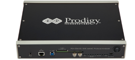
Prodigy Technovations has several different tools that interface with eMMC. The protocol analyzer is used to monitor the traffic that is happening on the bus. The eMMC protocol analyzer can capture the packets and help expedite debugging. This protocol analyzer can be used as an SD Protocol analyzer, SDIO protocol analyzer as well an eMMC protocol analyzer
The product features are as follows:
- Continuous monitoring of protocol data for a long time to capture elusive events (more than 30GB data capture)
- Analysis of captured data per standards for protocol integrity, count of data bursts, CMD CRC errors, Response CRC errors, Data CRC errors, Timing Values, and Reserved commands
- Hardware-based protocol-aware trigger capability in real time enables capturing specific Events. Triggering facility on patterns, commands, or error events.
- User can identify the anomalies by decoding command and response arguments
- Analytics feature provides analysis of acquired protocol data by plotting command, response, data, and frequency of operation over acquired time
- Analytics feature also provides the decoding of device registers for easy analysis
- Filters allow you to view specific packets in decoded protocol packets
- Search feature for specific events in protocol activity
- Easy-to-use user interfaces save time on the learning curve
- Handles long-duration capture and displays the decoded data without demanding extensive resources in the host computer
- Inserting markers [using Trigger-In] in protocol activity helps in correlating the input digital signal with Protocol Activity
- Trigger-out signal for any specific protocol event allows triggering of other instruments such as oscilloscope
- Interface to host system [running UI] using USB3.0 or Gigabit Ethernet interface
- Flexibility to upgrade the hardware firmware using the GbE interface provides easy field up-gradation of firmware
- Export of Decoded data packets to a Txt file for further analysis


