

UFS 4.0 Protocol Analyzer
Product
Overview
Datasheet
Presentation
Application
Notes
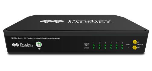
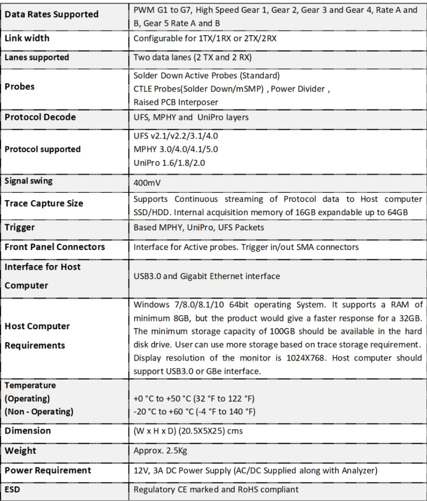
PGY-UFS4.0-PA, UFS Protocol Analyzer is the industry-first working and tested UFS4.0 Protocol Analyzer. It offers protocol data capture and debugging of data across MPHY, UniPro, and UFS protocol layers. It allows for instantaneous decoding of UFS, UniPro, and MPHY layers with the flexibility to correlate decoded data across these protocol layers. PGY-UFS4.0-PA supports PWMG1 to HSG5B data rates and two TX, and two RX lane decode. The active probe has minimum electrical loading on the device under test (DUT) and captures protocol data without affecting the performance of DUT. PGY-UFS4.0- PA Protocol Analyzer supports two-lane data. Comprehensive on the fly decoding of UniPro & UFS data enables validation of communication between UFS host and device.
PGY-UFS4.0-PA Protocol Analyzer allows Design and Test Engineers to obtain deep insight into UFS host and device communication. MPHY/UniPRO/UFS packet-based triggering allows specific protocol data capture and analysis. PGY-UFS Protocol analyzer instantaneously provides decoding of UFS, UniPro, and MPHY layers with a correlation to MPHY, UniPro, and UFS layers.
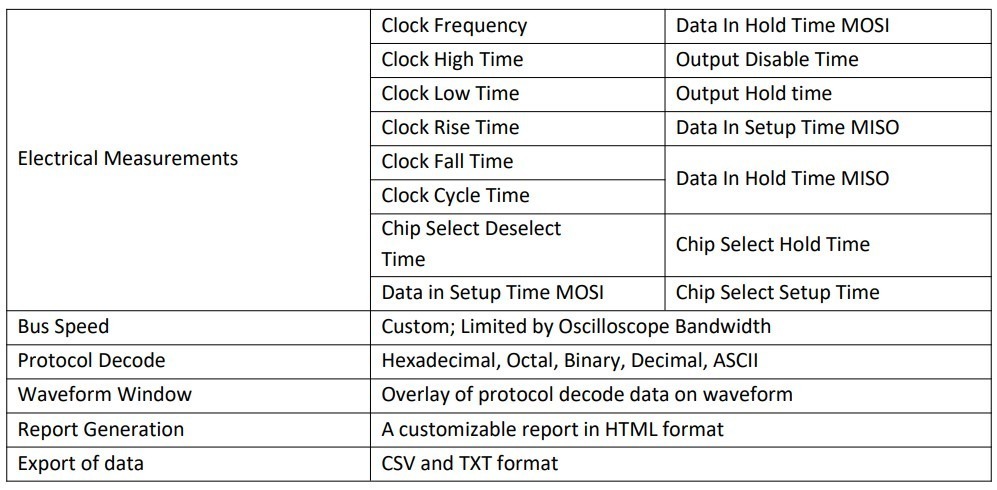
SPI Electrical Validation and Protocol Decode Software Datasheet
Key features
- Automated electrical measurements with a customizable reference level of SPI electrical signal.
- Automated measurements independent of the speed of SPI Bus
- Customizable measurement limit setup for pass/fail validation of electrical signal to enable measurements at different data speeds.
- Decodes SPI signals MOSI and MISO for easy understanding of protocol
- Links the protocol content to the electrical signal in the oscilloscope for easy understanding of the electrical characteristics of the protocol
- Overlays the protocol data on the analog waveform is a waveform plot window
- Zooms the selected SPI packet content in the decode table in the waveform plot waveform window for easy analysis of electrical characteristics of the I2C frame
- Ability to view protocol and decode data in hexadecimal, decimal, binary, octal, and ASCII formats
- Ability to store the SPI protocol data in CSV and txt format
- Utility features like zoom, undo, and fit the screen for easy debugging while correlating the protocol data to the waveform
- Report generation in HTML format
- Supports WFM and isf file formats for offline analysis.

Key Specifications
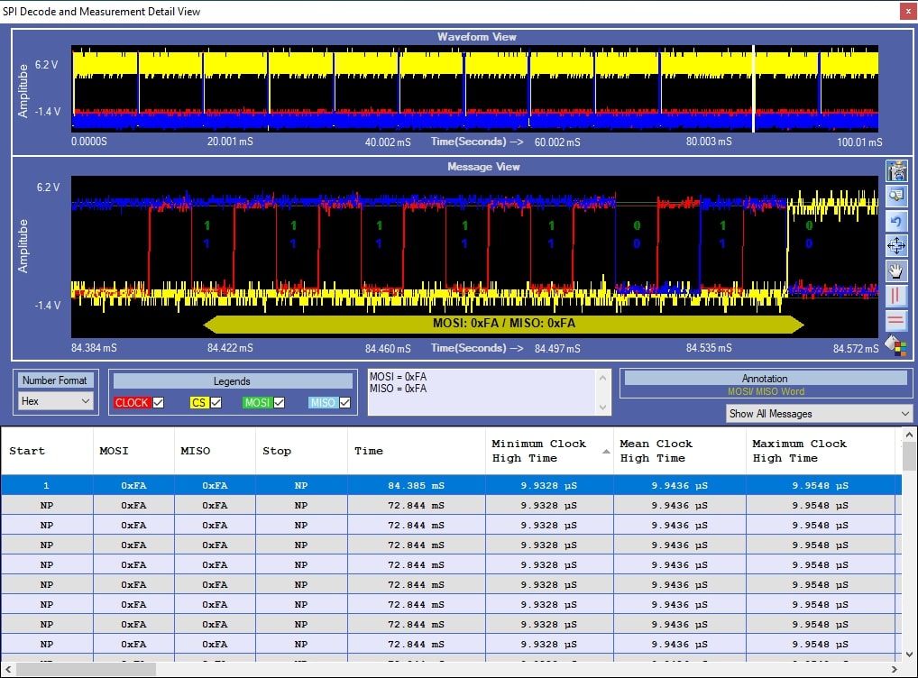
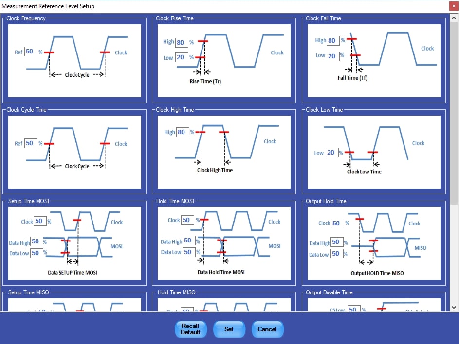
The PGY-SPI Electrical measurements and Protocol Decode Software offers electrical measurements and protocol decoding for SPI buses. This software provides the flexibility to set reference levels for electrical measurement and customized limits making it the most versatile solution to meet different needs of characterizing SPI Signals. Now design and test engineers can automatically make accurate and reliable electrical measurements and decode protocols in PGY-SPI software using data acquired by Tektronix DPO5000, TDS7000, DPO/DSA/MSO7000 oscilloscope series to reduce the development and test cycle.
Seamless Integration with Oscilloscope

PGY-SPI Software runs inside the Tektronix oscilloscopes and makes the electrical measurements, decodes protocols and displays the decoded data in a table, and links the decoded data to the electrical signal in the waveform plot. SPI Protocol-based trigger can be set up using the built-in SPI trigger capabilities in Tektronix oscilloscopes.
Reference Level Setup
Characteristics
