

UFS 4.0 Protocol Analyzer
Product
Overview
Datasheet
Presentation
Application
Notes
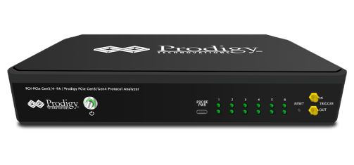
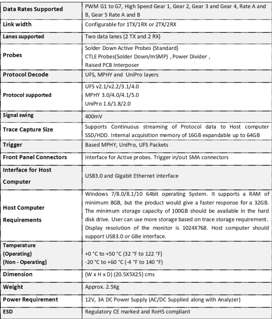
PGY-UFS4.0-PA, UFS Protocol Analyzer is the industry-first working and tested UFS4.0 Protocol Analyzer. It offers protocol data capture and debugging of data across MPHY, UniPro, and UFS protocol layers. It allows for instantaneous decoding of UFS, UniPro, and MPHY layers with the flexibility to correlate decoded data across these protocol layers. PGY-UFS4.0-PA supports PWMG1 to HSG5B data rates and two TX, and two RX lane decode. The active probe has minimum electrical loading on the device under test (DUT) and captures protocol data without affecting the performance of DUT. PGY-UFS4.0- PA Protocol Analyzer supports two-lane data. Comprehensive on the fly decoding of UniPro & UFS data enables validation of communication between UFS host and device.
PGY-UFS4.0-PA Protocol Analyzer allows Design and Test Engineers to obtain deep insight into UFS host and device communication. MPHY/UniPRO/UFS packet-based triggering allows specific protocol data capture and analysis. PGY-UFS Protocol analyzer instantaneously provides decoding of UFS, UniPro, and MPHY layers with a correlation to MPHY, UniPro, and UFS layers.
PGY-RFFE Protocol Trigger and Decode Analysis Software
Key features
- RFFE Protocol Analysis using oscilloscope live channel data or stored RFFE signals
- Powerful RFFE real-time protocol-aware hardware-based trigger capabilities
- Displays the decoded data in RFFE frame format
- Error checks for parity bits of command and data
- Error checks for Byte count with actual data count and missing SSC
- Flexibility to view Slave ID in Symbol or Hex value
- Flexibility to view decoded data in hex, binary, decimal, or octal format
- Long-duration data decode support to capture more RFFE protocol transactions
- Search capabilities to locate protocol event
- Filter capabilities to view information of Interest
- Documentation by exporting data in CSV and TXT file format
- Report Generation

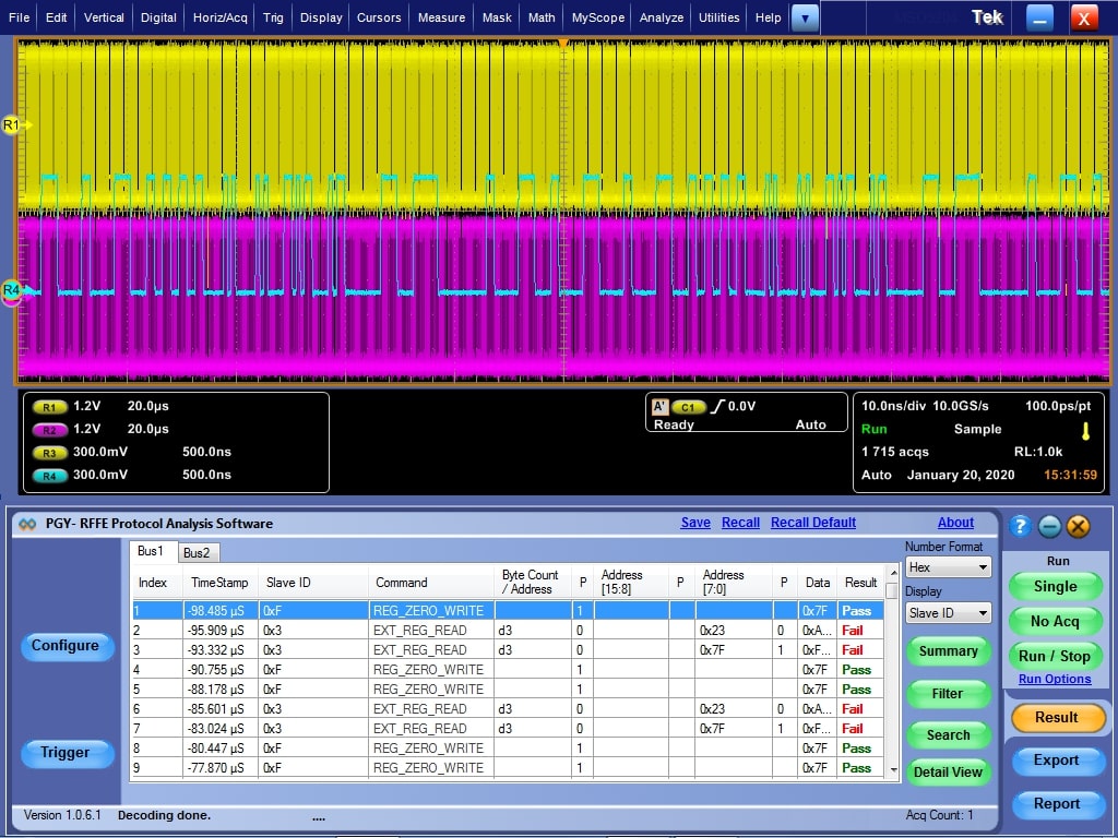
RFFE Protocol Decode Software offers protocol decoding as specified in the RFFE specification. PGY-RFFE Protocol decode software runs in Tektronix Oscilloscope and provides measurements for protocol decode at the click of a button. This allows engineers to quickly check for RFFE compliance and flexibility to debug the failure. In addition to this, engineers can decode the command and response of RFFE to debug the communication. PGY-RFFE takes advantage of the digital channels of MSO and provides the decoding of RFFE data lines.
PGY-RFFE Software runs on Tektronix oscilloscopes such as DPO/MSO5000, DPO7000, and DPO/DSA/MSO70000 oscilloscope series. PGY-RFFE utilizes the hardware-based real-time RFFE protocol aware trigger, and protocol analysis of long acquisition record lengths up to 125MB to provide superior RFFE Protocol Analysis results at the press of a button.
Easy RFFE Protocol Test Setup and Debug
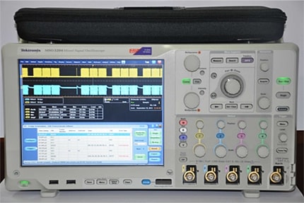
PGY-RFFE Software installed in Tektronix oscilloscopes can be launched by clicking the PGY-RFFE icon in the oscilloscope desktop folder. Now the user has simultaneous view and control of the oscilloscope as well as PGY-RFFE Software. Users can analyze RFFE in Single acquisition mode, Repetitive mode, and No Acq mode. In No Acq Mode, the RFFE software analyses an already captured RFFE signal that is present in the acquisition memory of the oscilloscope.
Powerful RFFE Protocol Aware Hardware-Based Real-Time Trigger
The simple, easy-to-use RFFE protocol-aware trigger feature allows engineers to capture RFFE signals at specific events in the RFFE interface.
Select any of the live channels Ch1 to CH4 as trigger sources and set the trigger pattern. The trigger can be set to full speed, half speed, or any custom data rate. RFFE provides the flexibility to select a combination of any one of the sixteen slave IDs, any command, and command-dependent parameters such as Byte count, Address, or Data.

The symbol table for Slave ID
Key Specifications
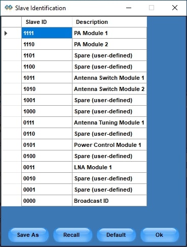
PGY-RFFE Software provides the flexibility to view the decoded data in the symbol table. RFFE specification documents provide guidelines to describe the Slave IDs. PGY-RFFE software has the default slave ID table. However, the user can edit the default table and apply the custom described slave IDs for easy analysis of protocol activities. This symbol table is used for easy trigger setup, protocol analysis, filter, and search features.
Protocol Analysis of RFFE Signals

RFFE Protocol decoded data is displayed as above. PGY-RFFE software processes up to 125MB record length and displays all the RFFE protocol packets. The software analyses each RFFE packet for missing SSC, and parity bit errors in address, command, and data bytes. PGY-RFFE software identifies any RFFE packet with missing SSC. This ensures that each RFFE packet meets the protocol specifications of RFFE. PGY-RFFE software displays the result for each RFFE protocol packet whether pass or fail.
Protocol Summary
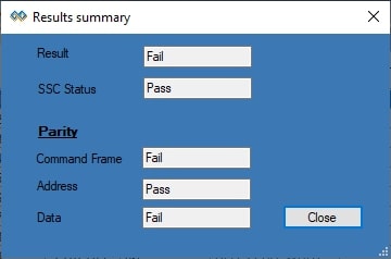
Protocol Summary provides a quick result view of protocol analysis of RFFE signals. This view lists the pass/fail status of SSC, parity bit in command, address, and data in the acquired data. This helps in locating the cause of RFFE Protocol packet failure.
Filter feature
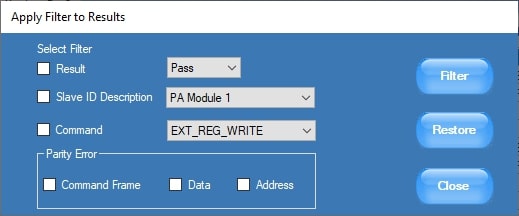
It is extremely challenging to view information of interest while there are hundreds of protocol transactions taking place between various devices. These problems compound during protocol analysis of a long record length. PGY-RFFE software solves this problem using the filter feature. By filtering information for Slave ID or specific command, or parity error type, the user can view only specific data of interest. Filters provide filtering of information using individual packet content or a combination of packet contents.
Search
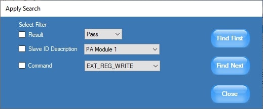
During protocol analysis, users tend to capture a large amount of data and capture any non-repeatable event. It is also extremely difficult to locate the RFFE packet of interest. RFFE Software’s Search filter is able to quickly locate the required Slave ID or command or Combination of both.
Documentation of Protocol Analysis
PGY-RFFE Protocol Trigger and Decode Analysis software provide flexibility to export the decoded data in txt and CSV file format. Report generation allows the user to include different waveforms images including the oscilloscope screenshot in a pdf report. Headers, comments, and test attributes can be added to the report.


