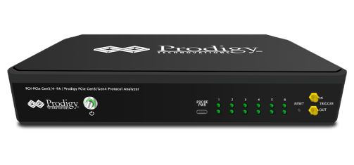


UFS 4.0 Protocol Analyzer
Product
Overview
Datasheet
Presentation
Application
Notes
PGY-UFS4.0-PA, UFS Protocol Analyzer is the industry-first working and tested UFS4.0 Protocol Analyzer. It offers protocol data capture and debugging of data across MPHY, UniPro, and UFS protocol layers. It allows for instantaneous decoding of UFS, UniPro, and MPHY layers with the flexibility to correlate decoded data across these protocol layers. PGY-UFS4.0-PA supports PWMG1 to HSG5B data rates and two TX, and two RX lane decode. The active probe has minimum electrical loading on the device under test (DUT) and captures protocol data without affecting the performance of DUT. PGY-UFS4.0- PA Protocol Analyzer supports two-lane data. Comprehensive on the fly decoding of UniPro & UFS data enables validation of communication between UFS host and device.
PGY-UFS4.0-PA Protocol Analyzer allows Design and Test Engineers to obtain deep insight into UFS host and device communication. MPHY/UniPRO/UFS packet-based triggering allows specific protocol data capture and analysis. PGY-UFS Protocol analyzer instantaneously provides decoding of UFS, UniPro, and MPHY layers with a correlation to MPHY, UniPro, and UFS layers.
QSPI Electrical Validation and Protocol Decode Software Datasheet
Key features
- Single and Dual Transfer rate (STR/DTR)
- Supports electrical measurements and compliance testing for Ext SPI, Dual SPI, and Quad SPI
- Supports Triggering on command index and on S# falling edge
- Supports Analog and Digital Channels of Tektronix MSO
- Automated electrical measurements with a customizable reference level of QSPI electrical signal
- Customizable measurement limit setup for pass/fail validation of electrical signal to enable measurements
- Ability to store the QSPI protocol data and electrical data in CSV and txt format
- Report Generation
- Supports offline analysis

Configuration Panel

Configure panel helps in selecting the Signal Source, Such as Channels, Wfm Files, and CSV Files (Digital). Live Analog or Digital Channels of the oscilloscope can be used for analyzing the signal. The software decodes the data and displays both the protocol data and electrical measurements as shown below. The offline analysis is made using the stored .wfm files (Analog channels data) or from CSV files (Digital Channel data).
Limit Setup Panel
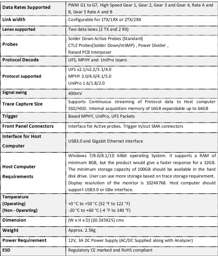
Key Specifications
The Limit Setup tab helps to set up the limits and reference levels of each selected measurement. In order to characterize and validate QSPI signals, PGY-QSPI software provides a graphical measurement reference level setup to set the measurement reference level of QSPI signals.

Electrical Measurements
PGY-QSPI software provides an extensive list of electrical measurements are (DTR not supported):
- Clock frequency for all commands other than reading
- Clock frequency for reading commands
- Clock High Time
- Clock Low Time
- Clock rise Time
- Clock fall Time
- S# active setup time (relative to the clock)
- S# not active hold time (relative to the clock)
- Data in setup time
- Data in hold time
- S# active hold time (relative to the clock)
- S# not active setup time (relative to the clock)
- S# deselect time after a READ command
- S# deselect time after a non READ command
- Output disable time
- Clock LOW to output valid under 30pF
- Clock LOW to output valid under 10pF
- Output hold time (clock LOW)
- Output hold time (clock HIGH)
- HOLD command setup time (relative to the clock)
- HOLD command hold time (relative to the clock)
- HOLD command setup time (relative to the clock)
- HOLD command hold time (relative to the clock)
- HOLD command to output Low-Z
- HOLD command to output High-Z
- Write protect setup time
- Write protect hold time
- Enhanced VPPH HIGH to S# LOW for extended and dual I/O page program
Protocol Decode
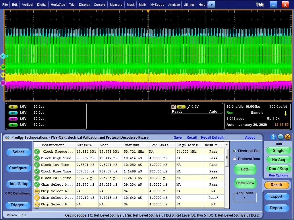
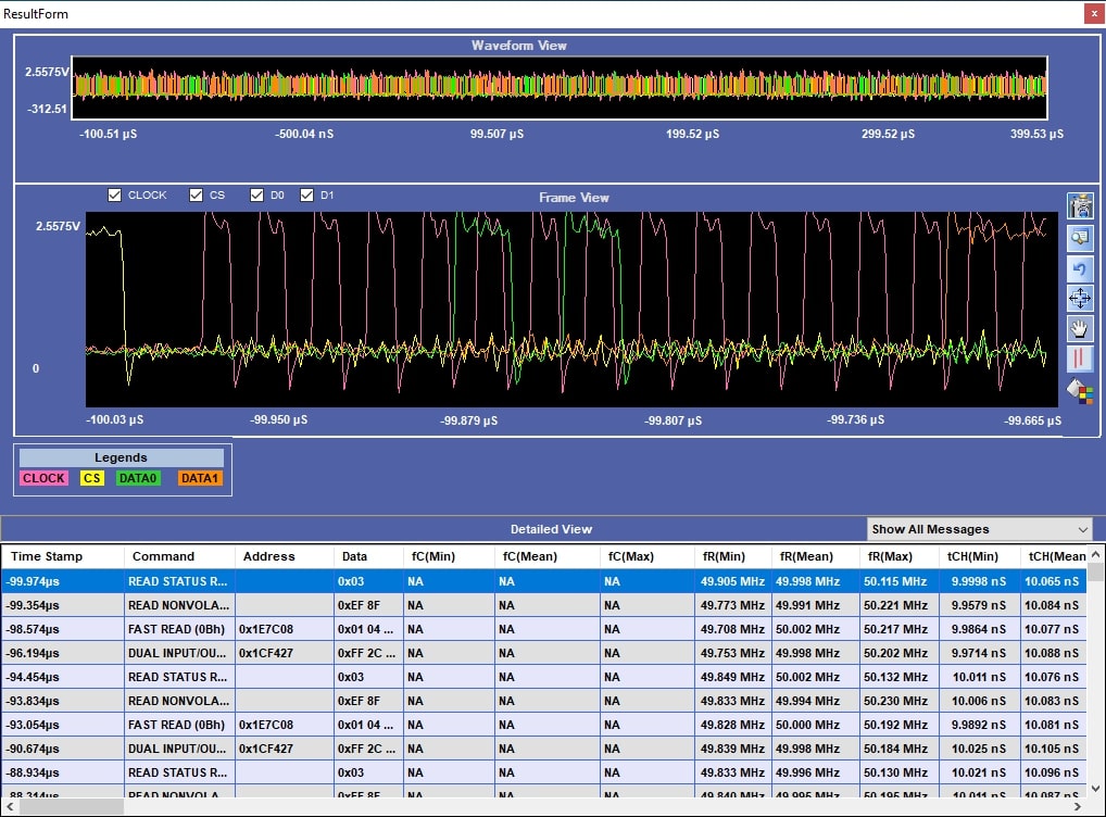
PGY-QSPI simultaneously decodes the QSPI signals along with electrical measurements. The software provides flexibility to view decoded commands, addresses, and associated data.
In detail, the view links the selected command to the electrical waveform for easy debugging of protocol-related problems.


