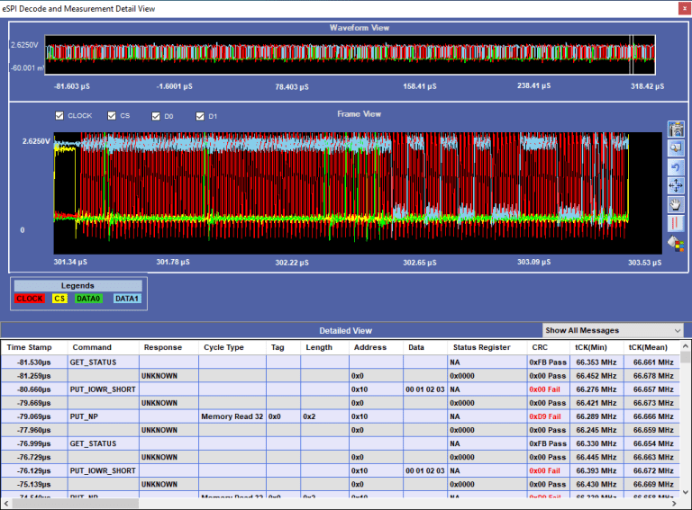
eSPI Electrical Validation and Protocol Decode Software offers electrical measurements compliance testing and protocol decoding as specified in eSPI specification. PGY-eSPI Electrical validation and Protocol decode software runs in Tektronix Oscilloscope and provides electrical measurements and protocol decode at the click of a button. This allows engineers quickly check for eSPI compliance and flexibility to debug the failure. In addition to this engineer can decode the command and response of eSPI to debug the communication. PGY-eSPI takes advantage of digital channels of MSO and provides the decoding of eSPI data lines.
Core Queries
Frequently Asked Questions
Core Queries
Frequently Asked Questions
You can purchase Prodigy Technovations solutions by submitting a Request a Quote on our website or by emailing us at contact@prodigytechno.com. Based on your requirements – such as protocol, data rates, and validation stage – our team will recommend the appropriate analyzer, exerciser, or electrical validation solution along with the required configuration.
Prodigy supports a broad range of serial bus and high-speed interfaces used in semiconductor and embedded systems. These include PCIe, UFS, I3C, eMMC, SD, SPI, QSPI, UART, and other serial interfaces. In addition, our tools support application and management layer protocols such as MCTP, SPDM, NVMe-MI, and PLDM over I3C, enabling full-stack validation.
Yes. Prodigy offers evaluation programs where engineers can test the tools in real validation environments. This includes use cases such as protocol decoding, traffic generation, error injection, and conformance testing. Evaluations are guided by our technical team to ensure your specific validation challenges are addressed.
Yes. Prodigy tools provide Python-based APIs and automation capabilities that enable repeatable validation workflows. Engineers can implement regression testing, automated traffic generation, protocol conformance checks, and long-duration stress testing as part of their validation pipelines.
Yes. Prodigy offers oscilloscope-based protocol decode and electrical validation software, allowing correlation between physical layer signal behavior and protocol-level events. This is critical for debugging signal integrity issues, timing violations, and link stability in high-speed interfaces.
Prodigy solutions support the complete validation lifecycle including IP design validation, protocol emulation, silicon validation, conformance testing, and system-level debug. These tools are widely used for interoperability testing, error injection, and corner-case validation across semiconductor, storage, automotive, and data center applications.
Download eSPI Electrical Validation and Protocol Decode Software Datasheet
"*" indicates required fields