Introduction
The next-generation cars are growing in complexity by providing advanced features on the infotainment and ADAS sub-systems. The next generation car is more becoming like a data center with subsystems communicating at very speed. Automotive ethernet enables fast In-vehicle communication to meet the rising demands of the future self-driving and autonomous cars. The term “Automotive Ethernet” can be used to refer to any Ethernet-based network for in-vehicle electrical systems. It includes 100Base-T1 as well as several other variants that are of different speeds and for different purposes. 100BASE-T1 is a 100Mbps automotive ethernet as defined by the IEEE 802.3bp specification.
Benefits
100BASE-T1 automotive ethernet offers higher bandwidth than most of the previous automotive serial data standards. Since it relies on a single, unshielded twisted pair, it also provides a low cost for cabling and reduces the cabling weight by around 30% compared to shielded cabling with connectivity cost savings of up to 80%. 100BASE-T1 also meets the EMC and EMI requirements, as well as the temperature grade requirements required in the automotive application space.
Automotive Ethernet Frame Structure:
The 100BASE-T1 frame is similar to the traditional ethernet frame but has some slight differences to support the point-to-point topology. One unique aspect of the 100BASE-T1 data frame is that it is marketed by a Start-of-stream delimiter (SSD) and an End-of-stream delimiter (ESD).
The SSD denotes the beginning of the frame. It is always represented by a code group 00,00,00. The code group 00 is reserved especially for the SSD and ESD and is not used anywhere else in data or idle mode. The SSD is followed by the preamble, which in 100BASE-T1 is shortened due to the insertion of the SSD. While the preamble is included, it provides a mechanism for synchronization at the beginning of the frame useful in large networks with a bus connection so that devices could easily synchronize their receiver clocks. But, In 100BASE-T1, It is only present for backward compatibility but not required because of the continuous connection in the point-to-point topology.
The preamble is followed by the Start-of-frame delimiter, or SFD which signifies the end of the preamble and the beginning of the traditional ethernet frame. In conventional Ethernet, the frame starts with a header, including the destination address and the source MAC address, but these are not critical for the 100BASE-T1 due to its point-to-point topology. The header also includes the EtherType field that provides directions on how to interpret the forthcoming data payload.
This is followed by the data payload which is followed by a frame check sequence (FCS), which is a 32-bit CRC used to detect any corruption of data.
The 100BASE-T1 frame ends with the ESD. The ESD can be transmitted in two different ways depending on whether the MII has indicated a tx_error during the data frame. An error-free ESD is represented by a code group 00,00,11. While a frame containing an error will end with 00,00,-1-1. Like the SSD these specific sequences are reserved for such purposes.
After the ESD, Idle symbols are again transmitted. The presence of the ESD in 100BASE-T1 shortens the interframe gap (IFG).
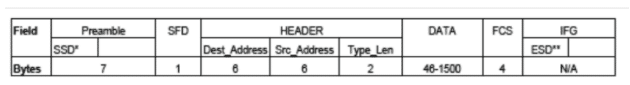
Figure 4. 100ASE-T1 Frame format
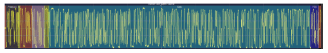
Figure 5. A 100BASE-T1 packet consisting of SSD and ESD denoted using red bars at the edges
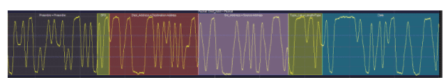
Figure 6. Following the Preamble and SFD the frame begins with the header that contains the MAC address as in legacy Ethernet. These are not necessarily required in point-to-point topology but are reserved to maintain backward compatibility.
Automotive Ethernet Theory of Operation:
100BASE-T1 uses a point-to-point topology directly connecting two nodes. The ‘-T1″ signifies that the signal is carried over a twisted pair of cables which in this case is an unshielded twisted pair. Unlike conventional ethernet types like 100BASE-Tx, 100BASE-T1 is a full duplex signal. Hence, the same pair will carry a bidirectional signal from a master to the slave. If this signal were to be observed using an oscilloscope alone it would not be possible to recognize which signal is from the master and which is from the slave, since both signals are transmitted simultaneously. A directional coupler is one solution to this and the other approach would be to decode traffic from one DUT independent of the other.
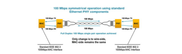
Figure 1. 100BASE-T1 Physical Topology
Automotive Ethernet Signaling:
100BASE-T1 uses PAM3 signaling. PAM stands for Pulse Amplitude Modulation and it uses the amplitude of the signal to encode the message information. PAM3 uses three distinct levels. The receiver sets a high and low threshold to determine the levels. Any samples above the high level are a +1 and a -1 below the low level and a 0 between the two levels. Signaling with three distinct values like in PAM3 is called a ternary signal or in the case of Automotive Ethernet a ternary symbol. In 100BASE-T1, two ternary symbols are combined to form a code group. When a code group is representing data, it represents 3 bits of data. The 100BASE-T1 specification defines how these code groups are mapped to the 3 bits.
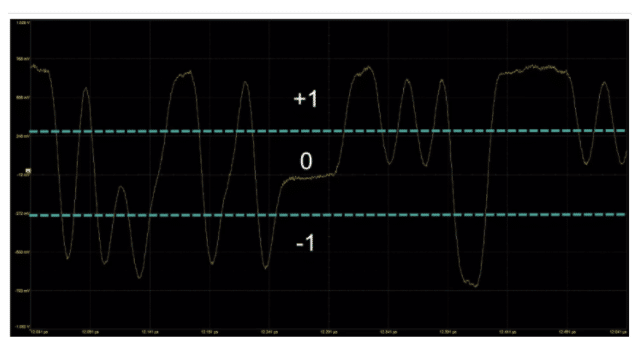
Figure 2. PAM3 Signaling
Automotive Ethernet Link Startup and Handshake
Upon power-up, The master and slave initiate a handshaking process to establish the link, called the link startup or link training process. The link startup uses three different signals
- SEND_Z – Denotes the transmission of all zeroes, called zero codes.
- SEND_I – Denotes the transmission of PAM3 idle signals.
- SEND_N – Denotes the transmission of PAM3 data or idle signals.
The handshake between the master and the slave will progress through these three types of signals. The link startup begins with the master transmitting PAM3 idle signals as it transitions from SEND_Z to SEND_I. During this time the slave continues to transmit SEND_Z. This allows the master to train its echo canceller, while the slave synchronizes to the master’s clock, locks its scrambler, and adjusts its signal conditioning.
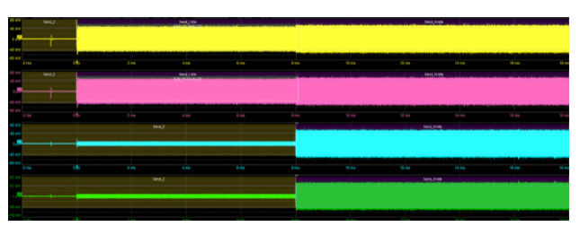
Figure 3. 100BASE-T1 Link Startup
In the above image, we can notice the 100BASE-T1 link startup showing the master in yellow and pink and the slave in blue and green switching from SEND_Z to SEND_I and SEND_N.
After this, the slave switches from SEND_Z to SEND_I while the master is still in SEND_I. This allows the slave to train its echo canceller, while the master locks its scrambler and adjusts the signal conditioning. The master and slave continue to send idle symbols (SEND_I) while they refine the timing, equalizer, and scrambler.
The last step is for the master and slave to validate that the link startup was successful by setting the scr_status, loc_rcvr_status, and rem_rcvr status. If these statuses are all validated, both the master and slave switch to the SEND_N state. If any of the above-mentioned statuses fail, the link startup restarts. The below image shows the completion of the link startup and the exchange of scrambler status messages.
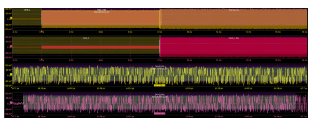
Figure 4. Link startup completion
Debugging Automotive Ethernet :
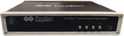
Debugging automotive ethernet remains a challenge. The engineer needs to understand the lower-level signaling as well the packet information. Prodigy Technovations provides an advanced protocol analyzer to debug automotive ethernet devices or interfaces with the ability to capture long-duration of packets.