UFS Protocol Introduction:
UFS stands for Universal Flash Storage. UFS is an advanced, high speed, low power, high-performance non-volatile interface designed for mobile systems such as smartphones and tablets UFS is an open standard and defined by JEDEC and incorporates standards from the MIPI alliance. UFS utilizes the SCSI architecture model supporting multiple commands, including command queuing enabling multi-threaded programming. UFS is the most advanced specification for both embedded and removable flash memory-based storage in mobile devices. The maximum I/O data rate for UFS is 1.45Gbps scalable up to 5.8Gbps.
Benefits OF UFS Protocol
1. Low energy consumption.
2. Low voltage differential signaling (LVDS) Interface.
3. Fast performance with a high-speed serial interface.
4. Reliable advanced physical, link, and command protocol layers.
UFS Protocol: Theory of Operation
UFS Interface:
UFS follows the Host and Device Model. The UFS Host initiates the transaction to the UFS Device. The data is transferred over a high-speed interface to the MPHY. The MPHY decodes high-speed serial data and passes it to the upper layer for further processing.

Figure 1. UFS Interface
UFS Protocol Architecture:
There are three major layers in the UFS architecture:
1.UCS
2 UTP
3.UIC (UniPro+ M-PHY).

Figure 2. UFS Layered Architecture
UFS Command Set layer (UCS):
The command set layer (UCS) is the interface to the software application and incorporates the SCSI standard as the baseline protocol for UFS specification.
UFS Transport layer(UTP):
The transport layer (UTP) is responsible for encapsulating the protocol into the appropriate frame structure for the interconnect layer.
UFS Interconnect layer:
The interconnect layer (UIC) is the lowest layer of UFS architecture. It handles the connection between the UFS host and the UFS device. UIC consists of MIPI UniPro and M-PHY.
UniPro
UniPro stands for Universal Protocol defined by MIPI. UniPro has four layers, Layer 1 is the physical layer, layer 2 the data link layer, layer 3 the network layer and layer 4 the transport layer. Layer 1 and 2 ensure the data integrity and reliability, layer 3 and 4 ensure that the data is routed to the intended UFS host or device.
M-PHY I/O
MIPI defines two types of M-PHY, type 1 and type 2.
Type 1 uses NRZ signaling for High speed (HS) and Pulse width modulation (PWM) signaling for Low Speed (LS)
Type 2 uses NRZ signaling for both High speed (HS) and Low speed (LS).
UFS utilizes two-speed modes, a high-speed mode, and a low-speed mode. M-PHY also supports multiple power states such as Stall (HS), Sleep (LS), Hibern8
Protocol layers of UFS Architecture

Figure 3. UFS Communication Architecture Layers
Application Layer
The application layer has three primary components: UCS layer, Task manager, and device manager. The UFS interface is designed to be protocol-agnostic. UFS supports a subset of SCSI commands. UCS handles SCSI commands supported by the UFS specification, the Task manager handles task management functions defined by the UFS that are meant for command queue control and the device manager handles device level operations and device configuration operations. Device-level operations constitute the device power management operations and commands to interconnect layers. Device-level configurations constitute the handling of query requests that are used to modify and retrieve configuration information of the device.
UTP LAYER
The UTP layer is responsible for providing services to the higher layers via service access points (SAPs). UTP defines three SAPs for higher layers:
UDM_SAP: The device manager SAP is to provide services for device-level operations. These device-level operations are done through query requests.
UTP_CMD_SAP: The command SAP is responsible for providing services to the UCS layer to transport commands.
UTP_TM_SAP: The task management SAP is responsible for providing services to the task manager to transport task management functions. UTP transports messages via the UFS protocol information unit.
UIC LAYER
UIC is the lowest layer of UFS architecture. It handles the connection between the UFS host and the UFS device. UIC consists of MIPI UniPro and M-PHY. UFS uses UniPro as its link layer and M-PHY as its physical layer.

Figure 4. UFS Host and Device
UFS is agnostic and offloads the link establishment, link reliability, and speed control between host and device. In UFS 3.0 MIPI M-PHY v4.1 and UniPro v1.8 form the UFS interconnect layer (UIC) that connects a UFS host to a UFS storage device. These two layers communicate over an RMMI Interface and can support two transmit and two receive lanes thereby giving a full duplex interface with the ability to simultaneously read and write data.
Debugging of UFS Protocol:
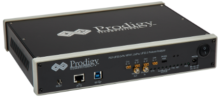
Debugging of UFS Protocol can be complex and challenging. Engineers need to not only understand the PHY-related challenges but also higher-level protocol data needs to be analyzed. Prodigy offers state of art UFS 4.0 protocol analyzer that can be used to debug complex high-speed protocols like UFS. The protocol analyzer supports UFS 3.0 and UFS 4.0 Protocol specifications.

UFS Protocol analyzer – https://prodigytechno.com/device/ufs-4-0-protocol-analyzer/


