Introduction to PCIe Express:
This blog describes the fundamentals of the Peripheral Component Interconnect Express (PCI Express) protocol. In personal computers, peripheral devices connect to the processor subsystem using Peripheral Component Interconnect (PCI), Peripheral Component Interconnect eXtended (PCI-X), Accelerated Graphics Port (AGP), and PCIe buses. Peripherals can be graphic cards, hard disk drives, SSDs, WiFi, and ethernet devices. PCIe replaces PCI, PCI-X, and AGP bus protocols used in computing machines of earlier days. The advanced version of PCI is PCI-express(PCIe). PCIe, PCI-e refers to PCI express protocol.
Comparison of PCI and PCIe:
Fig. 1 shows the legacy PCI and PCIe ports. PCI is a parallel interface whereas PCIe is a serial interface. PCI uses individual buses for each of the devices connected to it instead of a shared one like what PCIe uses.
The difference in speed between a standard PCI interface and 16 slot PCIe is large. The legacy PCI has a data rate of 133MB/s but the PCIe has a data rate of 16GB/s.
Also, PCI slots are the same sizes for all devices. PCIe slots differ depending on which form factor it accepts. The longest would be the 16-lane slot and, the shortest is for the 1-lane slots.
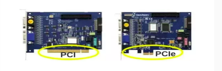
Fig. 1 PCI and PCIe slots on motherboards
Fig. 2 shows the topology of PCI and PCIe. Legacy PCI is a parallel data transfer protocol. But PCIe is a serial data transfer protocol.
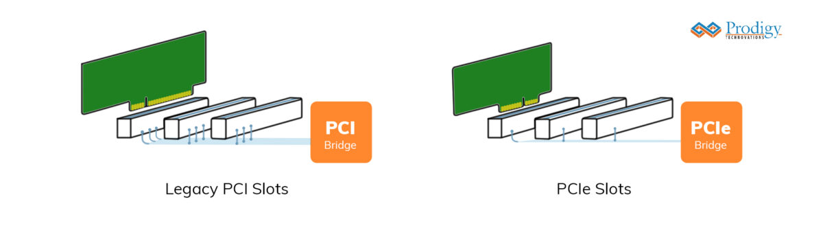
Fig. 2 Legacy PCI and PCIe slots topologies
PCI Special Interest Group (PCI-SIG):
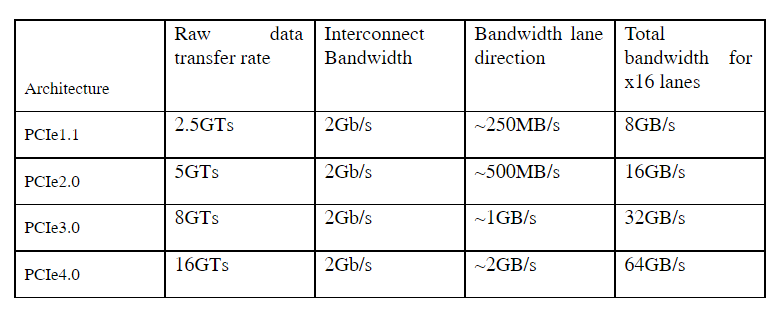
PCI-SIG defines and maintains the technical specifications and standards for PCI and PCIe. PCI-SIG is a special interest group of 900 companies. It defined PCIe in 1995 as PCIe 1.1. Since then, it has developed four versions of PCIe standards for improved architectures. PCIe supports high data throughput, and low power, and is of smaller size. PCIe makes today’s laptops, and computers smaller, making them powerful, portable, and handy. Lanes in PCI-e are many interfaces on which data transfers can happen in parallel. Laptop expansions and computer storage interfaces like SATA Express use PCI-e with many lanes. Table 1 shows the PCIe architectures and their bandwidth details:
Table 1 PCIe architectures and their bandwidth details
PCIe Features:
The main features of the PCIe protocol are:
- Point-to-point serial transfer protocol with master-slave configuration.
- Scalable with lane aggregation supporting multiples of transfer rates.
- Uses the same memory, IO, address space, and configuration as PCI and is compatible with it.
- Uses packet-based transaction protocol like ethernet
- It has improved data integrity with error handling
PCIe Pin descriptions:
PCIe comes in two configurations: 1 lane called PCIe x1 and 16 lane PCIe x16. It is a serial bus point-to-point protocol. General processors use the smallest PCI x1 slots. Graphic cards use the longest PCI x16 slots. PCIe x1 interface has 36 pins arranged in pairs of 18 pins. Out of 36 pins, only 6 pins are functional pins and the remaining are power or auxiliary pins. The six functional pins operate as differential pairs of signals. Differential signals are more immune to external interferences. They consume low power and help in clock recovery. PCIe x1 signal description is shown in Table 2.
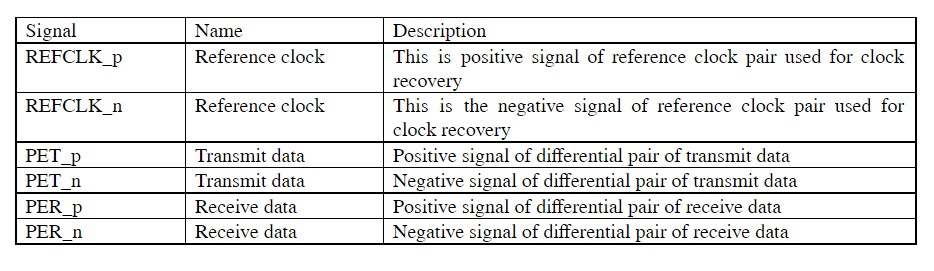
Table 2 PCIe 1x signal description
Multi-lane PCIe uses many of these functional signals except the REFCLK differential pair. For example, a two-lane PCIe uses five signal pairs with REFCLK and two PET, and two PER pairs. PCIe x16 uses thirty-three signal pairs.
PCIe stack
PCIe achieves reliable data transfers using a three-layer PCIe protocol stack as in Fig. 3.
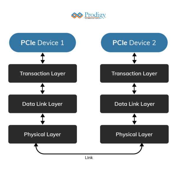
Fig. 3 PCIe protocol stack
The physical layer handles reliable transmission on the link with 8/10 encoding. The physical layer also does Clock recovery from the data it receives. Frequent data toggling ensures clock generation. But when the data is not toggling frequently, ten-bit data encoding toggles the data for this. A cyclic redundancy check (CRC) is used to help in correcting any data errors in the interface.
The data link layer checks received packets for packet errors with the help of retransmissions for errored packets and manage acknowledgments.
The transaction layer gets 32-bit words called double words (DWs) on the 32-bit interface from the master device which is sent as packets containing address, and data to the data link layer. Transaction layer DWs are called transaction layer packets (TLPs). TLP packet contains header and payload fields as shown in Fig. 4

Fig. 4 TLP packet structure
The detailed packet format is shown in Fig. 5
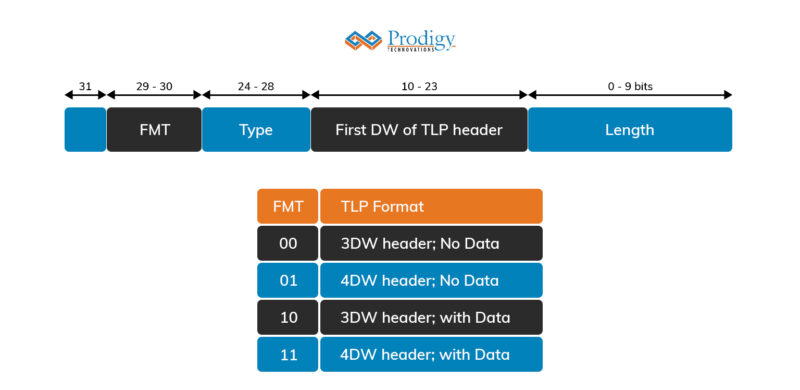
Fig. 5 TLP Detailed packet format
Data transfers:
PCIe transactions are requested and completions. There are four types of requests: Depending on the destination requests are classified as follows:
- Memory write/read
- IO write/read
- Configuration
- Message
Depending on whether they require completion, they are further classified as posted or non-posted requests. The request is non-posted if they do not need completion.
Memory or IO Data write:
When the master device wants to write 32-bit data onto the peripheral device, it initiates a write transfer request on the PCIe bus. This packet consists of a header, which is either 3 or 4 DWs long (depending on if 32 or 64-bit addressing is used) and one 32-bit DW to be written. Write-to memory happens in bursts. When the write requests are non-post requiring completion, the throughput reduces to Mbps as each write request must wait for completion. IO and configuration transactions are single transactions. When the PCIe master requests to read Memory, The PCIe device reads the data and responds to the master with the read data as completion with the data message.
Terminologies associated with PCIe:
Other terminologies associated with PCIe topologies are the following:
- Root Complex
- End Point
- PCIe bridge
- LTSSM
Root Complex: It is the “root” of the PCI inverted tree topology and acts on behalf of the CPU to communicate with the rest of the devices. It connects the system CPU to the PCIe topology. It initiates configuration requests as the requester. Fig. 6 shows the position of the root complex in PCIe topology.
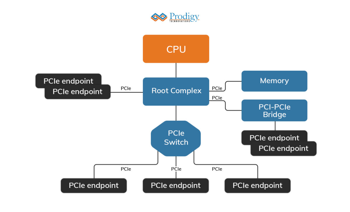
Fig. 6 Root complex position in PCIe topology
Endpoint: According to the PCIe specification in the PCIe topology there can be 256 buses, 32 devices on each bus, and 8 functions in each device.
An endpoint can support a maximum of up to 8 functions and every function has its own separate configuration space. A function in an endpoint can be a separate individual entity where it has its functionality. PCIe-based NVM and PCIe-based SSDs are two end-point devices on a computer system.
PCIe PCI bridge: They are adapters that allow PCI devices to connect to PCIe slots in systems by doing protocol conversions from PCI specification to PCIe 1x specification. The master sends requests with the necessary parameters to the PCIe bridge. PCIe bridge converts requests into point-to-point transfers on the requested lane in the interface.
LTSSM: LTSSM is an abbreviation of link training and the status state machine which manages PCIe devices. It is the main state machine control that detects, Polls, Configures, Recovers, Resets, and Disables the devices at the right times during operation.
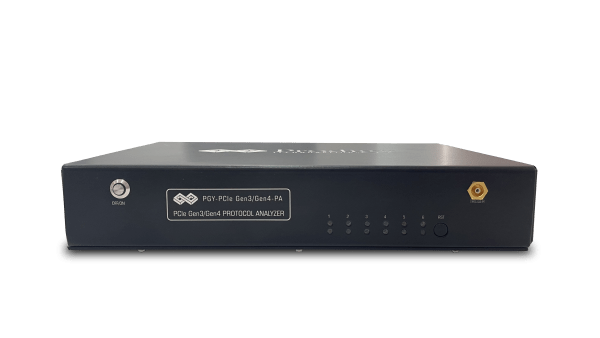
Debugging PCIe Protocol
Debugging PCIe Protocol can be a complex and challenging task for engineers. Prodigy’s cutting-edge PCIe Gen3/4 Protocol Analyzer is the solution you need for debugging high-speed protocols like PCIe.
With support for PCIe Gen3 and Gen4 specifications, our protocol analyzer provides advanced features to capture and analyze PCIe protocol data. It helps you identify and troubleshoot issues, ensuring optimal performance and reliability of your PCIe-based systems. Don’t let PCIe protocol debugging slow you down – empower yourself with Prodigy’s PCIe Gen3/4 Protocol Analyzer.