


Product
Overview
Datasheet
Presentation
Application
Notes
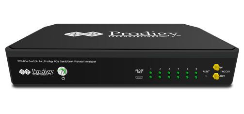
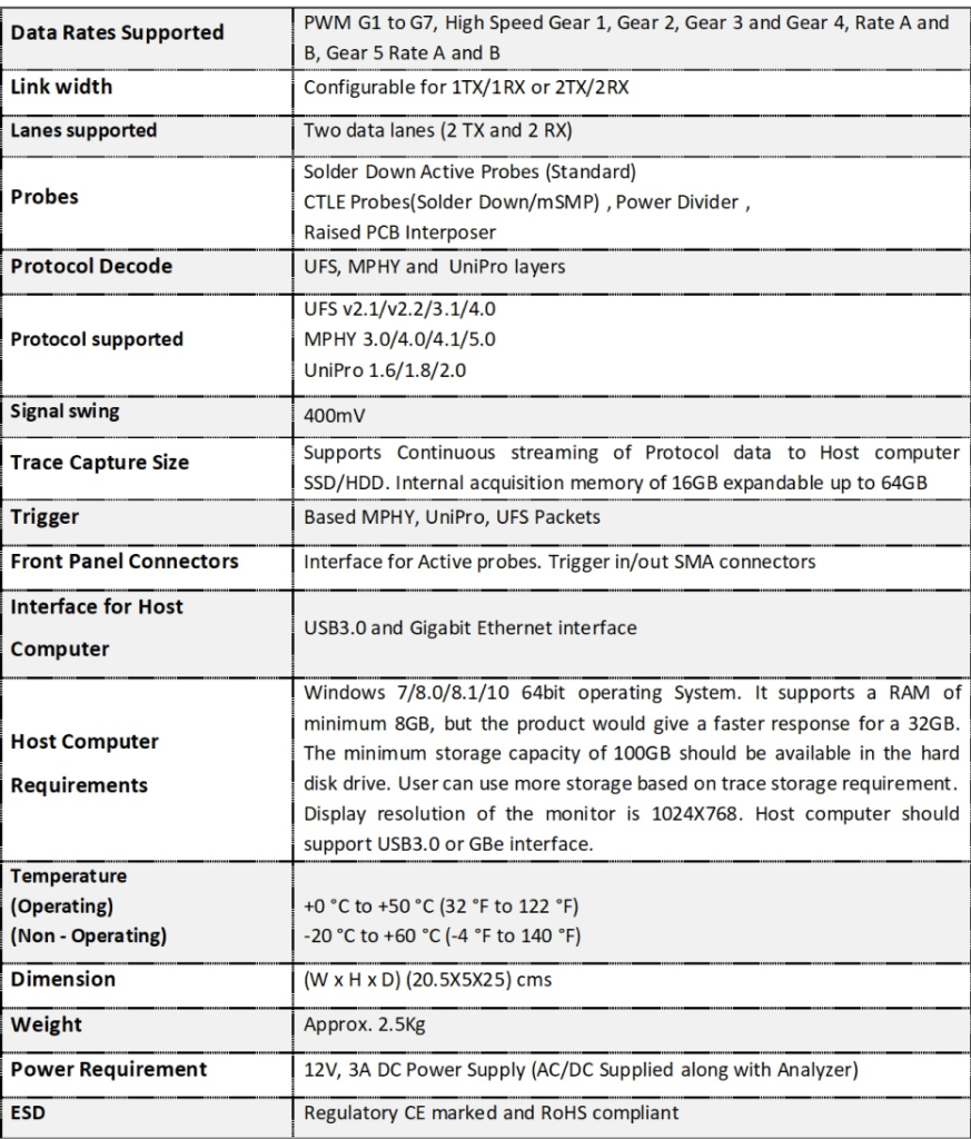
PGY-UFS4.0-PA, UFS Protocol Analyzer is the industry-first working and tested UFS4.0 Protocol Analyzer. It offers protocol data capture and debugging of data across MPHY, UniPro, and UFS protocol layers. It allows for instantaneous decoding of UFS, UniPro, and MPHY layers with the flexibility to correlate decoded data across these protocol layers. PGY-UFS4.0-PA supports PWMG1 to HSG5B data rates and two TX, and two RX lane decode. The active probe has minimum electrical loading on the device under test (DUT) and captures protocol data without affecting the performance of DUT. PGY-UFS4.0- PA Protocol Analyzer supports two-lane data. Comprehensive on the fly decoding of UniPro & UFS data enables validation of communication between UFS host and device.
PGY-UFS4.0-PA Protocol Analyzer allows Design and Test Engineers to obtain deep insight into UFS host and device communication. MPHY/UniPRO/UFS packet-based triggering allows specific protocol data capture and analysis. PGY-UFS Protocol analyzer instantaneously provides decoding of UFS, UniPro, and MPHY layers with a correlation to MPHY, UniPro, and UFS layers.
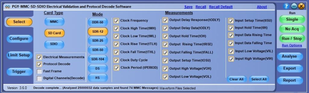
PGY- MMC and SD Electrical Validation and Protocol Decode Software run inside the Tektronix high-performance windows oscilloscopes. Automatically imports the data from oscilloscopes live channels. Also supports Tektronix .wfm and .isf file formats. This enables live and offline testing of eMMC and SD Signals.
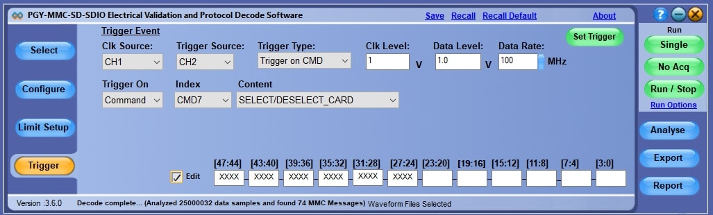
For efficient testing and debugging of eMMC/SD/SDIO, it is important to capture signals in the right condition. PGY-MMCSD software provides protocol aware triggering along the serial pattern trigger option of the oscilloscope to capture signals at specific events in the CMD line.
As per the specification of eMMC and SD, the measurement limits are different for reading and writing operations. The PGY-MMC-SD measurement algorithms automatically find the read and write operations and validate with the respective limits. This enables you to save time in identifying the read and write operation and isolating any compliance issues.
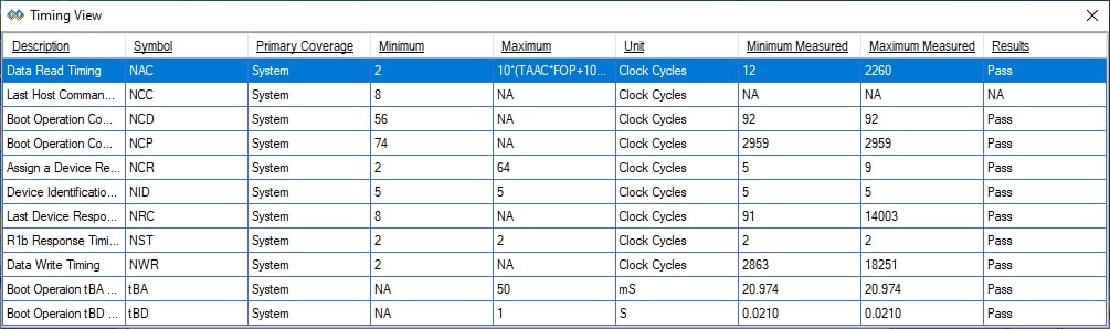
eMMC specifies the minimum and maximum cycles to present between the host and device to ensure interoperability. PGY-MMC-SD analyzes the data for these specifications and offers results.
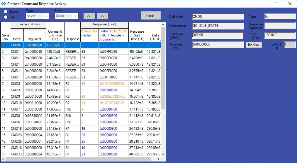
PGY-MMC-SD software lists all the protocol activity between the host and card. Engineers can now quickly view the command and its corresponding response from the card. Selected protocol activity details are listed on the right side of the list table. Now Engineers can know the errors reported by card or any other message to host without struggling to know the content of each message.
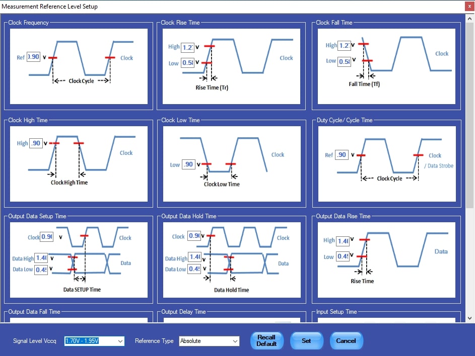
PGY-MMC-SD is not just for standard electrical compliance testing, you can also vary the limits and test your device with custom limits. The intuitive limits and reference level setup allows you to configure the limits and reference levels for your custom testing needs. This enables you to test your device beyond the specification and characterize it.
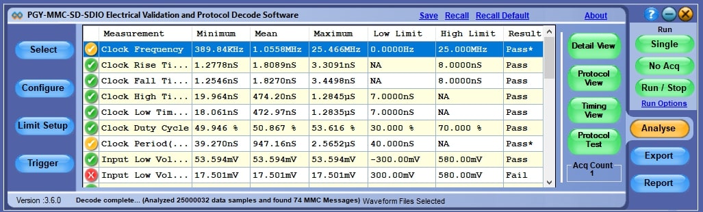
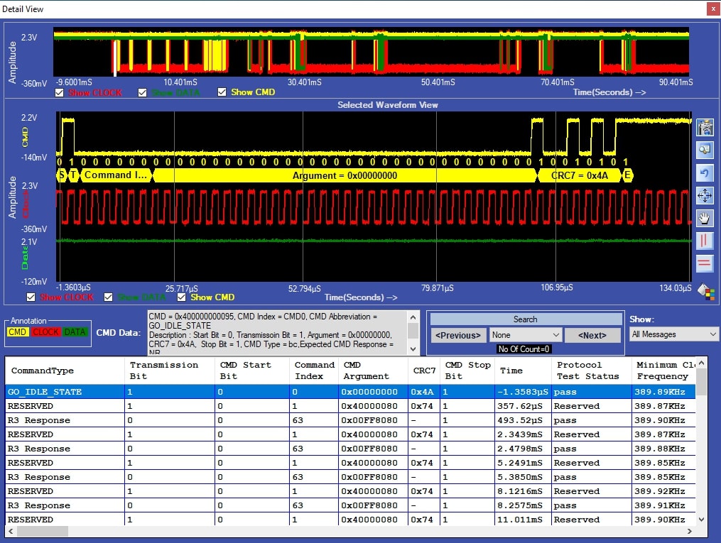
In Detail View, engineers can view the analog waveform, details of the protocol, and electrical measurements in a single view. If there is any failure in electrical measurement or error in protocol messages, designers can quickly correlate the protocol data with analog waveforms. These protocol errors can be caused due to the failure in electrical measurements. Users can select any row in the detail view; the corresponding analog waveform will be zoomed in and displayed. In the same row, engineers can view all the electrical measurements corresponding to the selected row. Utility features such as zoom, cursors, and markers make custom measurements while debugging.
Detail view provides the following capabilities:
PGY-MMC-SD leverages powerful capabilities of Digital Channels of MSO70000/5000 series oscilloscope to provide industry decoding of data signals in eMMC and UHS-I.
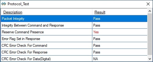
PGY-MMC-SD software automatically checks for Protocol Integrity. This allows a very easy method of ensuring protocol packets are as per protocol specifications of eMMC, and UHS-I Specifications.
| eMMC-HS DDR Measurements | Clock Frequency | Clock Low Time |
| Clock Rise Time | Clock Rise Time | |
| Clock Duty Cycle | Clock Duty Cycle | |
| Output Data Falling Time | Output Data Falling Time | |
| Input Setup Time | Input Setup Time | |
| Input Data Rising Time | Input Data Falling Time | |
| eMMC-HS SDR Measurements | Clock Frequency | Clock Low Time |
| Clock Rise Time | Clock Fall Time | |
| Output Data Falling Time | Output Data Rising Time | |
| Input Setup Time | Output Delay Time | |
| Input Data Falling Time | ||
| eMMC HS-BC Measurements | Clock Frequency | Clock Low Time |
| Clock Rise Time | Clock Fall Time | |
| Clock Duty Cycle | Output Setup Time | |
| Output Hold Time | Output Delay Time | |
| Input Setup Time | Input Hold Time | |
| eMMC HS-200 Measurements | Clock Period | Data Read Setup Time |
| Clock Rise Time | Data Read Hold Time | |
| Clock Fall Time | Command Output Delay | |
| Clock Duty Cycle | Data Write-Output Delay | |
| Response Setup Time | Command Valid Window | |
| Response Hold Time | Data Write Valid Window | |
| SD-DDR Measurements | Clock Frequency | Clock Low Time |
| Clock Rise Time | Clock Fall Time | |
| Clock Duty Cycle | Output Setup Time | |
| Output Delay Time | Input Hold Time | |
| Input Setup Time | ||
| Bus Speed | Supports all Data speeds; Limited by oscilloscope Bandwidth | |
| Protocol Decide | Protocol View and Detail View | |
| Waveforms Plots | Analog signals plotted with Bus diagram in for Protocol format for correlation of PHY information to Protocol data | |
| Report Generation | PDF format report generation | |
| Export of Data | Export to CSV and TXT format | |
| Oscilloscope file format | WFM and ISF file format of Tektronix oscilloscope | |
Our team represents a talented, experienced, and highly specialized group of development engineers, sales and marketing specialists. Through many years of direct engineering involvement with our customers, our personnel have developed expertise in wide range of technologies in serial data.
Prodigy Technovations Pvt Ltd
#294, 3rd Floor, 7th Cross, 7th Main, BTM II Stage,Bangalore – 560 076 | India
+91 80 4212 6100
contact@prodigytechno.com
© 2023 Prodigy Technovations. All Rights Reserved
PGY-UFS4.0-PA, UFS Protocol Analyzer is the industry-first working and tested UFS4.0 Protocol Analyzer. It offers protocol data capture and debugging of data across MPHY, UniPro, and UFS protocol layers…